Magnetic noise reduction method for AC rotary electric machine, and motor control apparatus and AC rotary electric machine apparatus using the same

Active Publication Date: 2005-04-07
DENSO CORP
View PDF11 Cites 82 Cited by
  • Summary
  • Abstract
  • Description
  • Claims
  • Application Information

AI Technical Summary

Benefits of technology

In a preferred mode (claim 34), the harmonic PWM signal generating means performs processing to output to the inverter a harmonic PWM signal having frequencies 7 and 13 times the frequency of the fundamental frequency component of the stator current and a harmonic PWM signal having at least either one of frequencies 19 and 25 times the frequency of the fundamental frequency component, and thereby attenuates the magnetic sound of the three-phase AC rotary electric machine as the AC rotary electric machine that has frequencies 6 and 12 times the frequency of the fundamental frequency component and the magnetic sound of the three-phase AC rotary electric machine as the AC rotary electric machine that has at least either one of frequencies 19 and 25 times the frequency of the fundamental frequency component, as compared to the case where the processing is not performed. This achieves an AC rotary electric machine that is quieter in operation.
In a preferred mode (claim 35), when I1 denotes the amplitude of the fundamental frequency of the stator current, In denotes the amplitude of the harmonic current of the stator current, and t, x, and y respectively denote prescribed phase angles, the fundamental frequency component of the stator current contains at least a first phase fundamental frequency component Iu1 (=I1 sin(θ)), a second phase fundamental frequency component Iv1 (=I1 sin(θ−x)), and a third phase fundamental frequency component Iw1 (=I1 sin(θ−y)), and the harmonic current whose frequency is n times contains at least a first phase harmonic component Iun (=In sin n(θ+t)), a second phase fundamental frequency component Ivn (=In sin {n(θ+t)−x}), and a third phase fundamental frequency component Iwn (=In sin {n(θ+t)−y}), wherein the first p

Problems solved by technology

However, the above prior art magnetic noise reduction techniques of the harmonic superimposing type, despite its name, have fallen far short of being able to reduce the noise of AC rotary electric machines to a satisfactory level.
However, the above prior art documents do not provide concrete descriptions about the numerical relations between the acoustic energy (vibration energy) to be reduced and the electric current (or power) to be supplied, that is, the parameters defining the frequency, phase, and amplitude (magnitude) of the electric current or power that should be applied to the armature coil of the AC rotary electric machine in order to reduce the magnetic noise (acoustic energy) at a designated frequency, and it is therefore not known what electric current should be applied to reduce the magnetic noise of a particu

Method used


Image

  • Magnetic noise reduction method for AC rotary electric machine, and motor control apparatus and AC rotary electric machine apparatus using the same
  • Magnetic noise reduction method for AC rotary electric machine, and motor control apparatus and AC rotary electric machine apparatus using the same
  • Magnetic noise reduction method for AC rotary electric machine, and motor control apparatus and AC rotary electric machine apparatus using the same

Examples


configuration example 1

CIRCUIT CONFIGURATION EXAMPLE 1

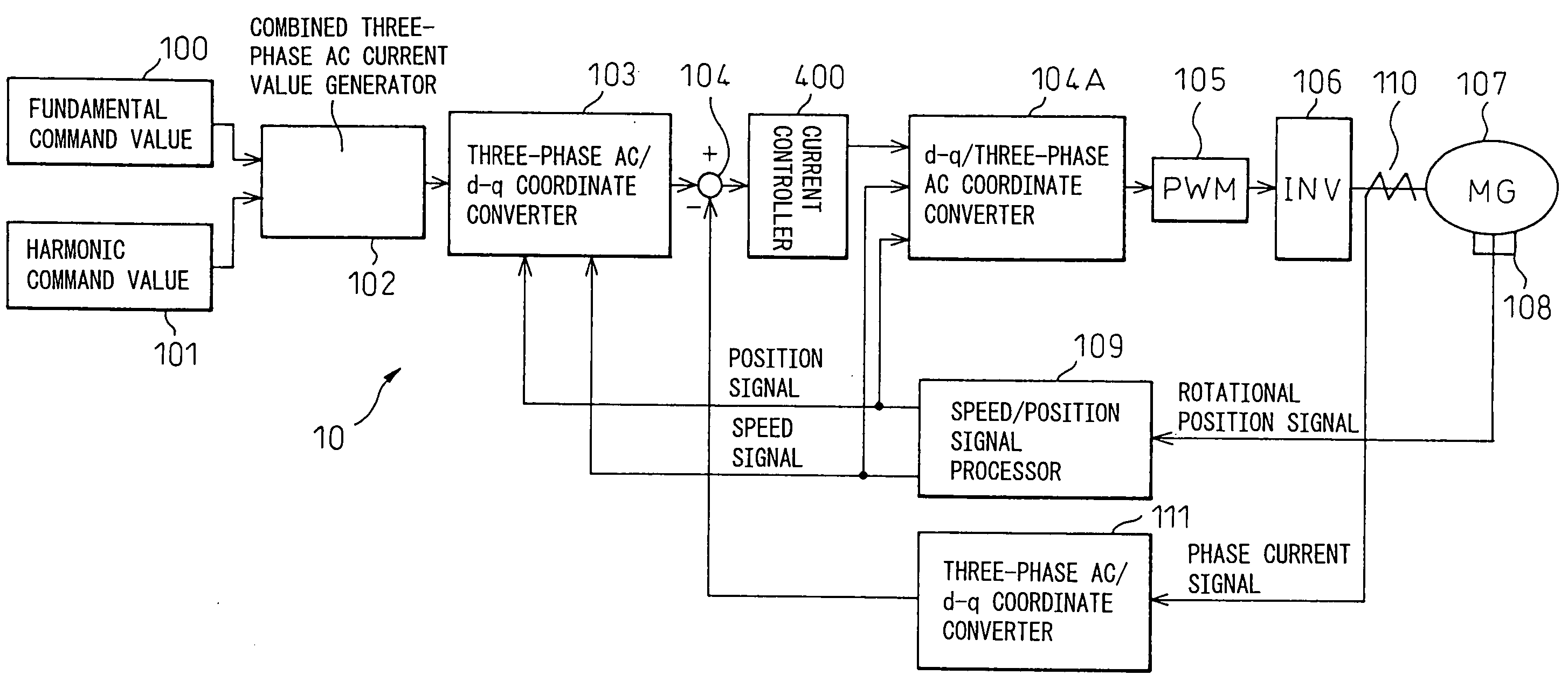
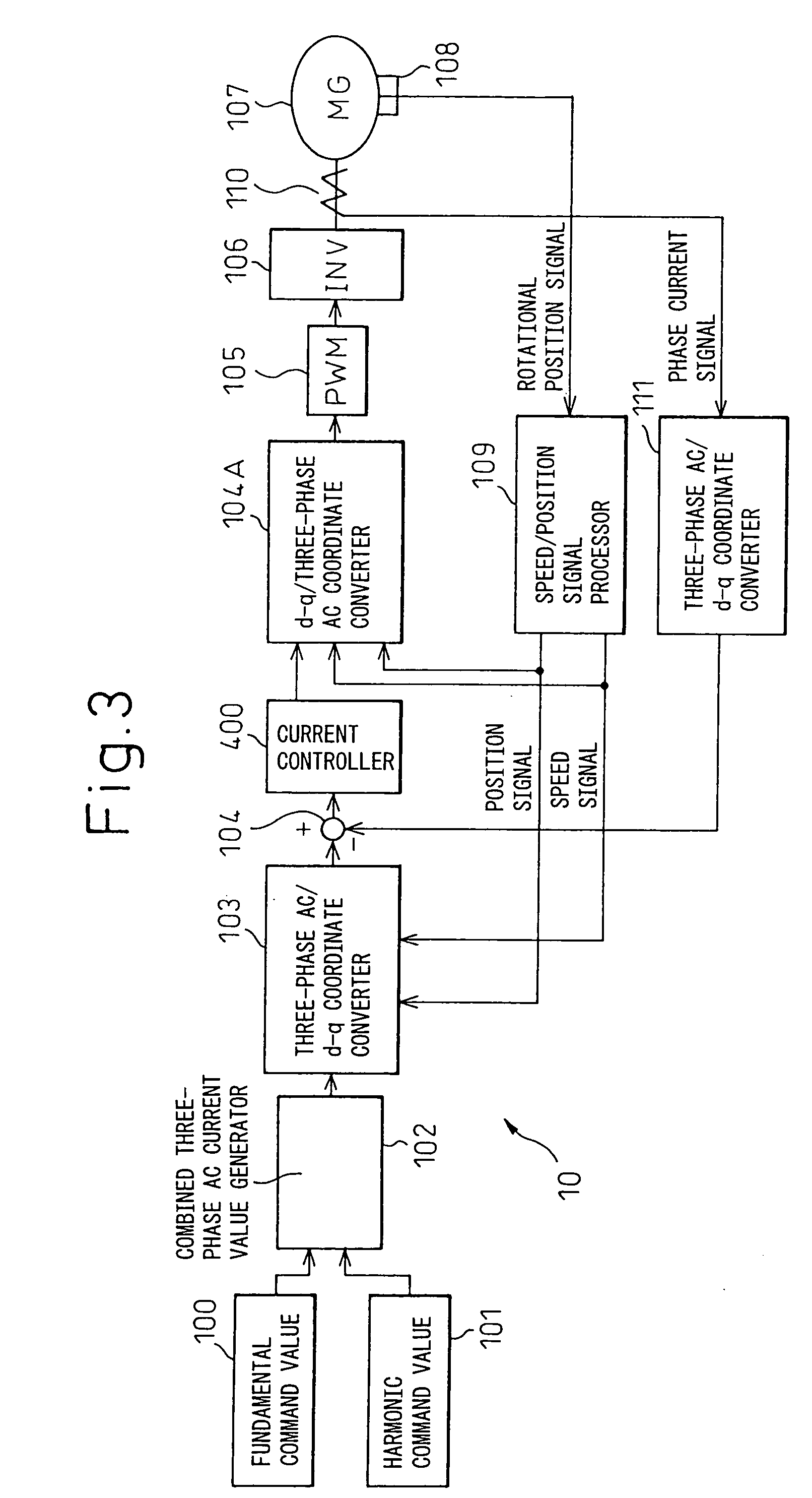
An example of the circuit for superimposing the above-described harmonic currents is shown in FIG. 3. The motor control circuit shown here is an embodiment that performs the feedback control of the motor current.

Reference numeral 10 is a motor current control means for controlling the motor current of a three-phase synchronous machine 107, and has the following configuration.

Reference numeral 100 is an amplitude / phase commanding circuit block which commands the amplitude and phase of an electric current command value (in three-phase AC coordinate system) corresponding to the fundamental wave. Reference numeral 101 is an amplitude / phase commanding circuit block which commands the amplitude and phase of a harmonic current of a designated order (in three-phase AC coordinate system).

The amplitude / phase commanding circuit block 100 determines the amplitude and phase based on the current command (fundamental wave) received from an external control app...

configuration example 2

CIRCUIT CONFIGURATION EXAMPLE 2

An example of the circuit for superimposing the above-described harmonic currents is shown in FIG. 4.

Reference numeral 100 is an amplitude / phase commanding circuit block which determines amplitude and phase as an electric current command value (in three-phase AC coordinate system) corresponding to the fundamental wave. The command value output from the circuit block 100 is fed to a subtractor 104a via a circuit block 300 which performs conversion from the three-phase AC coordinate system into the d-q axis coordinate system as in the first circuit configuration example. An FFT 111 extracts the detected value of the fundamental component (in three-phase coordinate system) from the phase current output from the current detector. The detected value is first converted by a circuit block 403 from the three-phase AC coordinate system into the d-q axis coordinate system, and then compared in the subtractor 104a with the electric current command value, and t...

configuration example 3

CIRCUIT CONFIGURATION EXAMPLE 3

An example of the circuit for superimposing the above-described harmonic currents is shown in FIG. 5. The circuit shown here employs a filter 113 replacing the FFT 111 shown in FIG. 4, and extracts a fundamental current detection value and a harmonic current detection value.

From the phase current signal detected by the current sensor 110, the detected value of its fundamental component (in three-phase coordinate system) is extracted. The detected value is first converted by the circuit block 403 from the three-phase AC coordinate system into the d-q axis coordinate system, and then compared in the subtractor 104a with the fundamental electric current command value, and their difference is supplied to the coordinate converting circuit block 104B via the gain-adjusting current controller 401. The circuit block 104B outputs a three-phase AC current command value for eliminating the above difference to the adder 112.

A subtractor 117 subtracts the fund...


PUM


Abstract

The invention provides techniques for reducing or altering the magnetic noise of an AC rotary electric machine. A magnetic noise reducing harmonic current of order n, whose frequency is n times the frequency of the fundamental frequency component of a polyphase AC current fed to an armature of a polyphase AC rotary electric machine, is superimposed on the polyphase AC current, thereby reducing or altering a harmonic component having a frequency (n−1) times the frequency of the fundamental frequency component and occurring due to a radial magnetic excitation force acting radially on an iron core of the AC rotary electric machine. Magnetic noise is caused by a vibration whose energy is the sum of the circumferential and radial vibrations of the iron core occurring due to the magnetomotive force of the rotor, and altering the radial vibration is particularly effective in altering the magnetic noise; as the harmonic component of the radially acting magnetic excitation force, occurring due to harmonic components having frequencies 3, 5, 7, and 13 times the fundamental frequency, has a frequency 6 or 12 times the fundamental frequency, the magnetomotive force of the rotor can be effectively reduced or altered when a current having a frequency 7 or 13 times the fundamental frequency is superimposed on the stator current.

Description

CROSS REFERENCE TO RELATED APPLICATION This application is based upon and claims the benefit of priority from the prior Japanese Patent Application No. 2002-303650, filed on Oct. 17, 2002, the prior Japanese Patent Application No. 2002-303651, filed on Oct. 17, 2002, the prior Japanese Patent Application No. 2003-323779, filed on Sep. 16, 2003, and the prior Japanese Patent Application No. 2003-323782, filed on Sep. 16, 2003, the entire contents of which are incorporated herein by reference, and a continuation of PCT / JP03 / 13303. TECHNICAL FIELD The present invention relates to a magnetic noise reduction method for an AC rotary electric machine, and to a motor control apparatus and AC rotary electric machine apparatus using the same. BACKGROUND ART Electric vehicles, hybrid vehicles, fuel-cell vehicles, etc. are currently in the development or in the practical implementation stage. These vehicles employ high-output AC rotary electric machines as primary means for generating vehicl...

Claims


Application Information

Patent Timeline
IPC IPC(8): H02J3/01H02K19/36H02P21/00H02P21/05H02P29/00
CPCH02J3/01H02K19/36Y02E40/40H02P21/00H02P29/0038H02M1/44H02P29/50
Inventor YOSHINAGA, SOICHIWAKABAYASHI, KENICHITAKAI, TAKATOSHIMORIOKA, TATSURUTSUJI, HIROYAOKAMURA, MAKOTOYAMAKAWA, SHINOBU
Owner DENSO CORP
Why Eureka
Try Eureka