
Polymer matrix composite

a polymer matrix resin and composite technology, applied in the direction of cell components, non-conductive materials with dispersed conductive materials, connection contact material materials, etc., can solve the problems of reduced service rating, poor adhesion to polymer matrix resins, and low modulus of elasticity and poor abrasion resistance, so as to enhance fiber orientation and the effect of large length to width ratio

Inactive Publication Date: 2005-04-07
OHIO UNIV
View PDF11 Cites 21 Cited by
  • Summary
  • Abstract
  • Description
  • Claims
  • Application Information

AI Technical Summary

Benefits of technology

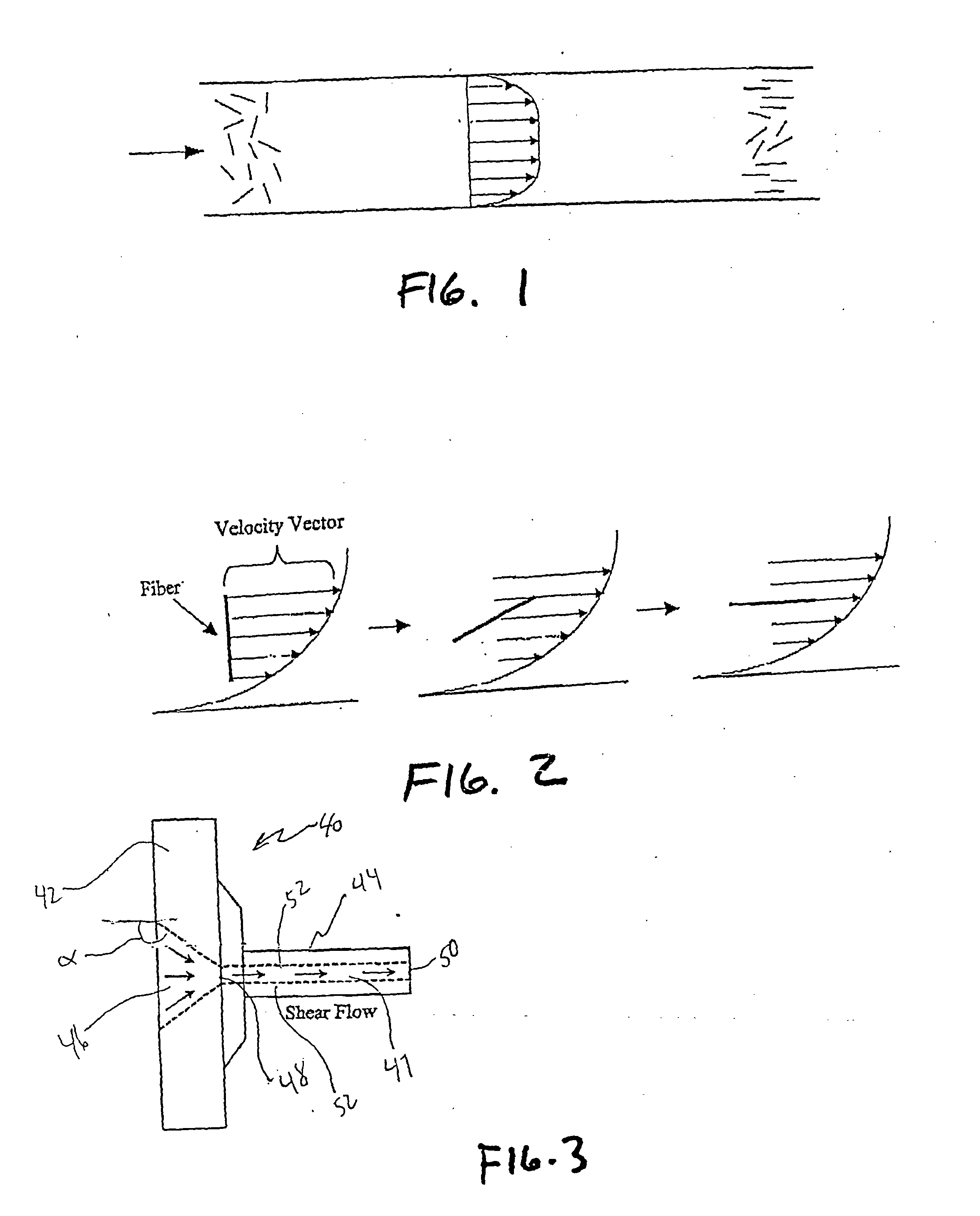
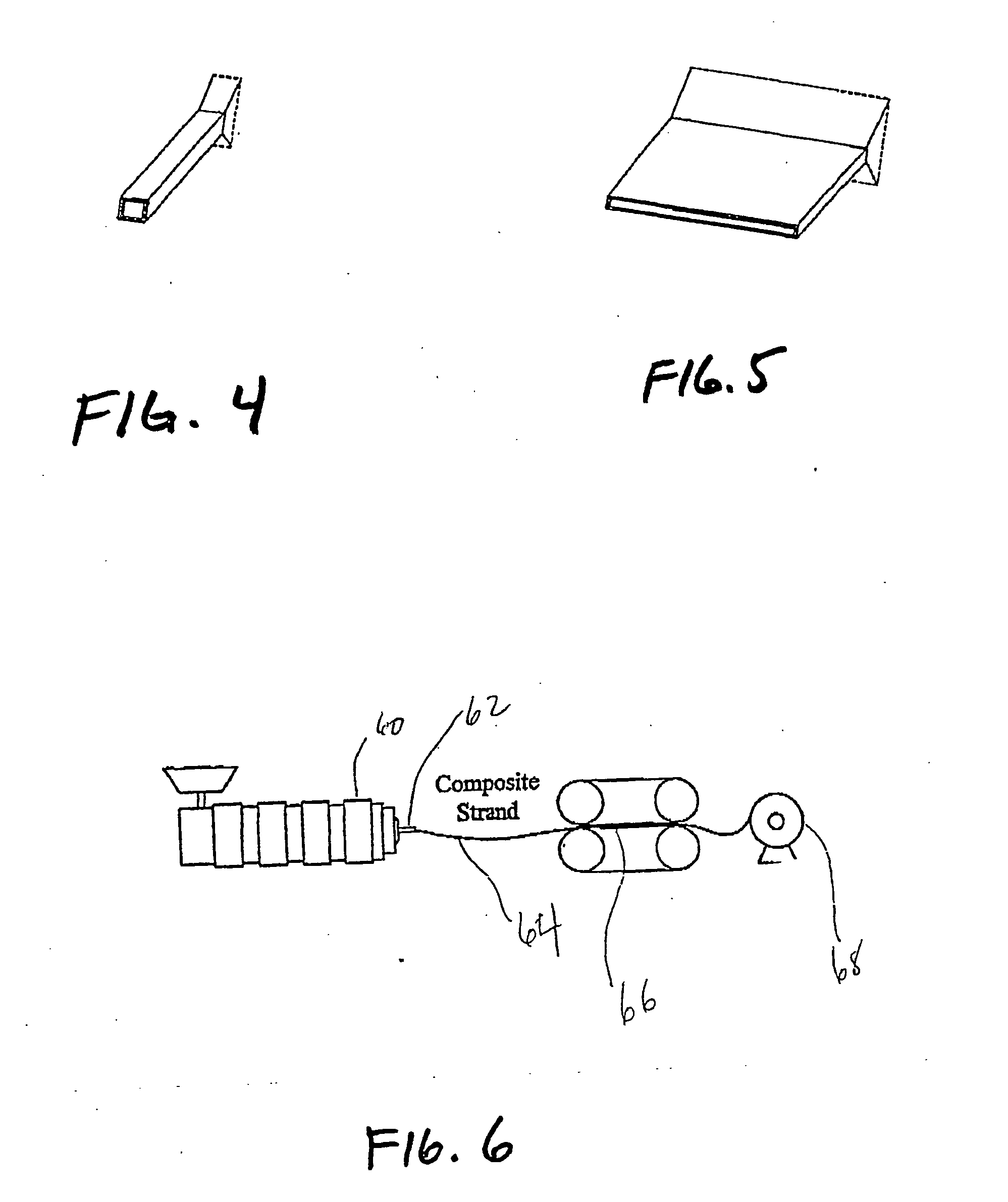
These and other objects are accomplished by the present invention which is based on the discovery that very short fibers can be easily oriented in polymer matrix composites by extruding a mixture of the fibers and matrix polymer through a die having a large surface to volume ratio, typically at least about 10 in−1 and more normally at least about 50 in−1.
In a preferred embodiment of the invention, the die also has a large length to width ratio as it has been further found that this enhances fiber orientation even more.

Problems solved by technology

The disadvantages of glass fibers is that they have a relatively low modulus of elasticity and poor abrasion resistance.
This results in a decrease in service rating and poor adhesion to polymer matrix resins, especially in the presence of moisture.
Pitch-based fibers are of lower quality and inferior properties, but are currently the lowest-cost carbon fiber on the market.
When compared to glass fibers, carbon fibers offer higher strength and modulus, lower density, outstanding thermal and electrical conductivity, but are much higher in cost.
The high cost of producing carbon fibers is the principle barrier prohibiting carbon fiber reinforced composites from wider commercial application.
Moreover, because of their relative low cost, they have the potential to replace glass and other reinforcing fibers currently used in cost-sensitive commercial markets.
However, vapor-grown carbon fibers become randomly aligned and entangled during production.
However, most of these techniques are effective only if the fibers are either continuous or above some minimum length.
When the fibers become very short, for example on the order of 100 microns (0.1 mm) or less in length, these methods become largely ineffective.
However, the orientation achievable in Daimaru is inherently limited by the maximum draw ratio of the extrudate, while the Tepic approach is unattractive from a commercial perspective.

Method used


Image

  • Polymer matrix composite
  • Polymer matrix composite
  • Polymer matrix composite

Examples


working examples

The following working examples are provide to more thoroughly illustrate the present invention.

Fiber Alignment

To evaluate polymer matrix composite articles formed in accordance with this invention, test specimens were formulated containing 1 to 23% volume fraction vapor-grown carbon fiber made in accordance with the above-noted Tibbetts et al. patent, U.S. Pat. No. 5,024,818. The fibers had a diameter of about 0.2 micrometers and lengths ranging from 50 to 100 microns and were manufactured by Applied Sciences, Inc., (“ASI”) of Cedarville, Ohio, under the name PR-21-AG. They are essentially soot-free and are characterized by having an apparent density of less than about 0.02 grams per cubic centimeter. The fibers were dried in a vacuum oven at approximately 300° C. for duration of about 3 hours to assure removal of moisture and volatiles. They were then thoroughly mixed in a dual-shell dry blender with Pro-Fax 6301, a polypropylene homopolymer manufactured by Montell U.S.A. Inc....


PUM

PropertyMeasurementUnit
surface to volume ratioaaaaaaaaaa
lengthaaaaaaaaaa
lengthaaaaaaaaaa

Abstract

Fiber-reinforced polymer matrix composites with anisotropic properties are produced by extruding a mixture of very short fibers and a polymer through a die having a surface to volume ratio of at least about 10 in−1.

Description

TECHNICAL FIELD OF THE INVENTION The present invention relates to polymer matrix composites with high strength, high thermal conductivity and high electrical conductivity as well as to processes for making these composites. BACKGROUND Many types of reinforcing fibers are currently used in composite materials. Glass fibers are the most common reinforcing fibers for polymer matrix composites due to their low-cost and high strength. They are commonly referred to as “basic” composites and are used in many high-volume applications, particularly the automotive industry. The disadvantages of glass fibers is that they have a relatively low modulus of elasticity and poor abrasion resistance. This results in a decrease in service rating and poor adhesion to polymer matrix resins, especially in the presence of moisture. The so-called “advanced” composites, which are made from carbon, aramid, boron, or other high modulus fibers, are used primarily for more exotic aerospace and military appli...

Claims


Application Information

Patent Timeline
Patent Type & Authority Applications(United States)
IPC IPC(8): B29C48/08B29C70/14H01B1/24H01M4/137H01M4/36H01M4/60H01M4/62H01M4/64H01M4/86H01M4/88H01M4/96
CPCB29K2301/10Y02E60/122H01M4/137H01M4/364H01M4/602H01M4/625H01M4/64H01M4/8652H01M4/8864H01M4/8875H01M4/96Y02E60/50B29C47/0004B29C47/0021B29C70/14B29K2105/06B29K2105/14H01B1/24B29C48/022B29C48/08Y02E60/10
Inventor ALAM, M KHAIRULKURIGER, REX J
Owner OHIO UNIV
Learn More