System and method for dispensing a volatile liquid fertilizer

a technology of volatile liquid fertilizer and system, which is applied in the field of system and method for dispensing volatile liquid fertilizer, can solve the problems of high failure rate, difficult to accurately control and measure the flow rate of ammonia, and increase so as to reduce the pressure of fertilizer

Active Publication Date: 2005-04-14
CAPSTAN
View PDF0 Cites 24 Cited by
  • Summary
  • Abstract
  • Description
  • Claims
  • Application Information

AI Technical Summary

Benefits of technology

For instance, the flow rate of the volatile liquid fertilizer entering the dispensing tubes can be controlled by a plurality of constant pressure flow rate control devices. The constant pressure flow rate control devices control the flow rate of the fertilizer without significantly reducing the pressure of the fertilizer within the distribution manifold.
Of particular advantage, the above system is not only well suited to dispensing volatile liquid fertilizers but is equally well suited to dispensing non-volatile liquid fertilizers. Thus, different types of fertilizers may be dispensed from the system without significantly modifying any of the components.

Problems solved by technology

A common problem with the above described system, however, is that the flow rate of the ammonia is difficult to accurately control and measure due to vaporization of the ammonia as it moves through the system.
Further drawbacks to such turbine type flow meters is that a high failure rate is seen due to over speeding the turbine when vapor is surged through the system, usually upon startup.
The ammonia still vaporizes as it enters the distribution manifold creating other various problems.
This problem is especially magnified at lower pressures and flow rates where greater degrees of vaporization are more likely to occur.
Besides failing to maintain uniformity in the distribution of ammonia between the individual lines, the above described system also only operates within a narrow range of ammonia flow rates.
Pressure variation of the ammonia in the system, however, is limited to the range between the maximum pressure in the tank and the minimum pressure which can maintain the ammonia in a liquid state.
Consequently, wide ranges of application rates are simply not practically possible.
Prior art systems have also failed to provide individual control of the flow of ammonia to each knife.

Method used


Image

  • System and method for dispensing a volatile liquid fertilizer
  • System and method for dispensing a volatile liquid fertilizer
  • System and method for dispensing a volatile liquid fertilizer

Examples


example

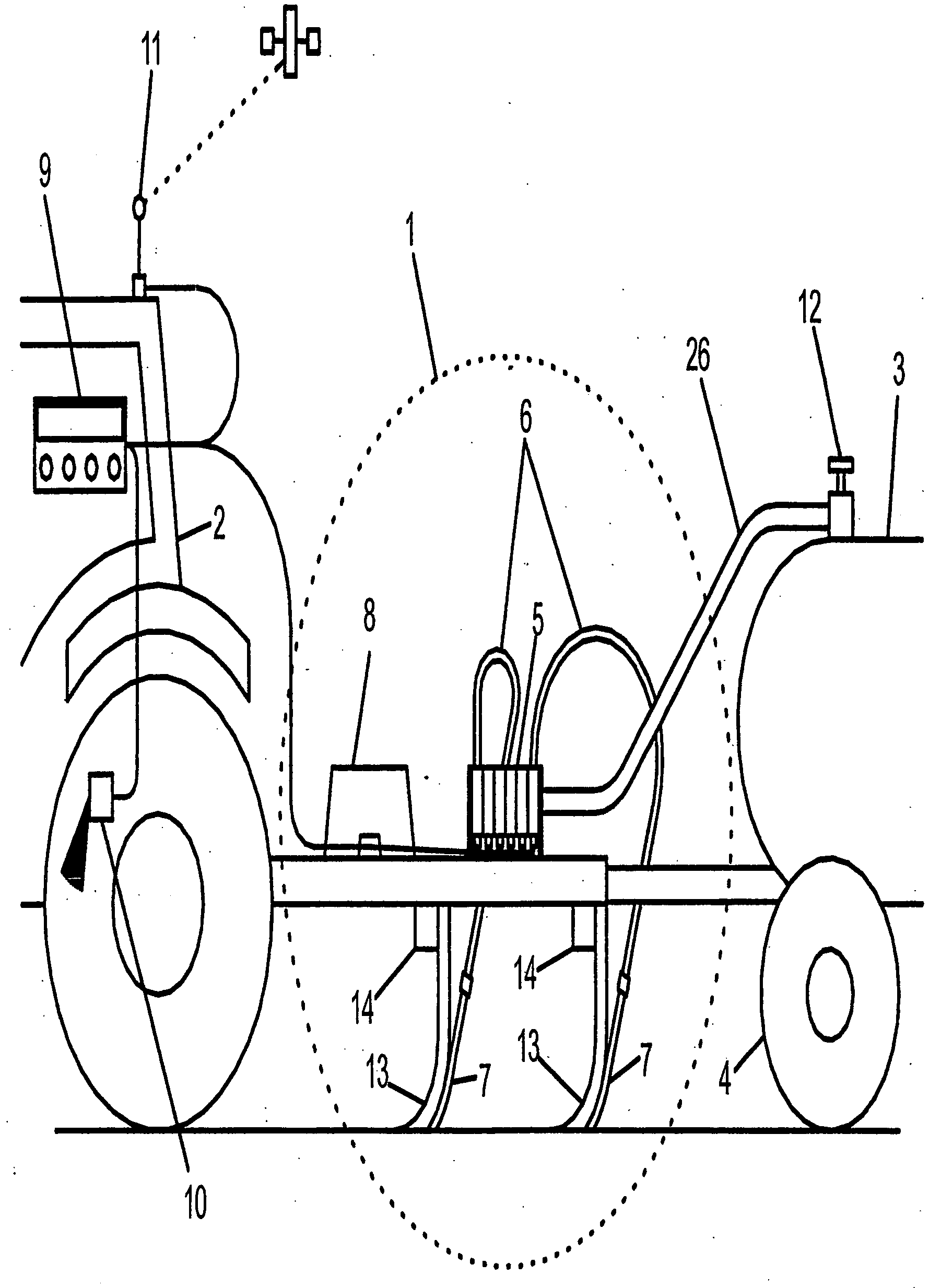
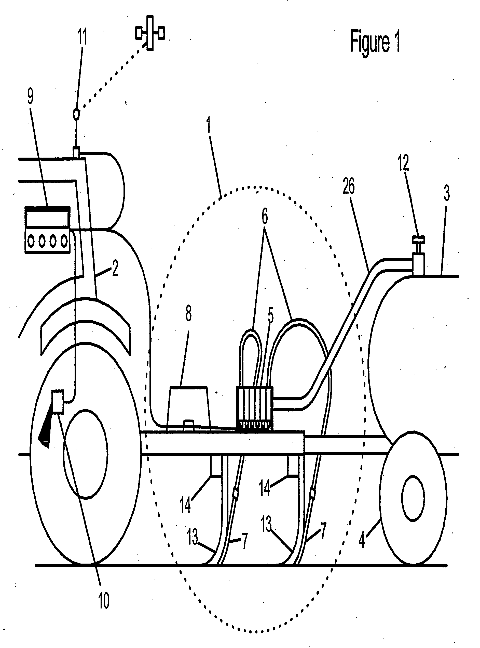
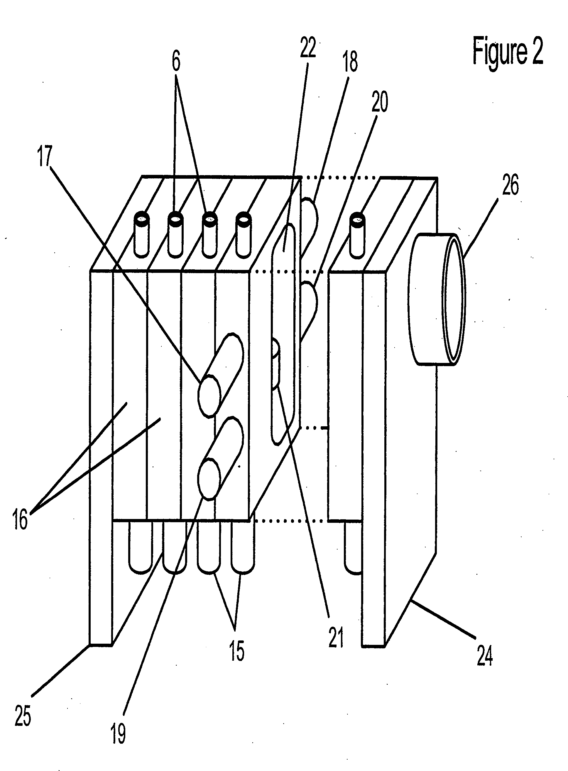
A liquid fertilizer distribution system as shown in FIG. 1 was manufactured and tested. The system included a multi-plate stacked valve system point and was comprised of a set of aluminum segments. Each segment included two valves so that the number of plates could be varied to produce a desired number of outlets. In this embodiment, constant pressure flow rate control devices were used to dispense liquid fertilizer into dispensing tubes.

The inlet side of the constant pressure flow rate control devices operated very close to the tank pressure and the discharge side operated at pressures less than about 400 kPa.

The constant pressure flow rate control devices had an orifice that was 2.36 mm in diameter. The diameter of the outlet increased from 2.36 mm to 6.35 mm. The outlet passage had a diameter of 12.7 mm.

Each of the constant pressure flow rate control devices included a valve plunger that was lifted by a 14 watt, 12-VDC coil. The coils were actuated by a 3 Hz CAPSTAN SHARPS...


PUM


Abstract

A system and process for dispensing a liquid agrochemical such as ammonia into a field is disclosed. The ammonia is placed in a vessel under sufficient pressure to maintain a substantial portion of the ammonia in a liquid form. From the pressurized vessel, the ammonia is fed to a distribution manifold where it is ultimately injected into a soil through a plurality of dispensing tubes. A constant pressure flow rate control device is placed at each dispensing tube for metering the amount of ammonia fed to the soil. Furthermore, the outlet flow of each constant pressure rate control device is made to vaporize nearby the inlet flow path to create a heat exchange effect thereby cooling the inlet flow. In particular, the flow control devices allow ammonia to be dispensed from the system while maintaining sufficient back pressure and temperature within the distribution manifold to maintain the ammonia in a liquid form. By maintaining the ammonia in a liquid form, uniform and accurately controlled flow rates can be dispensed from the dispensing tubes.

Description

FIELD OF THE INVENTION The present invention generally relates to a system and to a process for applying a liquid fertilizer to soil. For instance, in one embodiment, a system is disclosed that uniformly applies ammonia to soil. The system operates at a wide range of flow rates, offers fast response times when changing flow rates, and allows the application rates to be precisely controlled and varied in response to changing circumstances. BACKGROUND OF THE INVENTION Anhydrous ammonia (NH3) is commonly used as a soil fertilizer, since it is the most concentrated practical form of nitrogen. In conventional systems, when applying ammonia to soil, ammonia is placed in a tank under pressure. The tank is placed on a trailer and towed by a tractor. Some of the ammonia in the tank vaporizes creating pressure. This pressure is not only used to maintain most of the material in a liquid form, but is also used to force or pump the liquid from the tank. In particular, liquid ammonia in the ta...

Claims


Application Information

Patent Timeline
Patent Type & Authority Applications(United States)
IPC IPC(8): A01C23/02
CPCY10S111/90A01C23/024
Inventor GRIMM, JEFFREY JOHNHENDERSON, GRAEME W.KOLB, TROY CHRISTMANN
Owner CAPSTAN
Why Eureka
Try Eureka