
Cooling of liquid fuel components to eliminate coking

a liquid fuel component and cooling system technology, applied in mechanical equipment, machines/engines, light and heating apparatus, etc., can solve the problems of inoperable valves, flow restrictions, coke formation in liquid fuel pipes, etc., and achieve the effect of reducing the temperature of fuel oil components

Inactive Publication Date: 2005-04-21
GENERAL ELECTRIC CO
View PDF49 Cites 7 Cited by
  • Summary
  • Abstract
  • Description
  • Claims
  • Application Information

AI Technical Summary

Benefits of technology

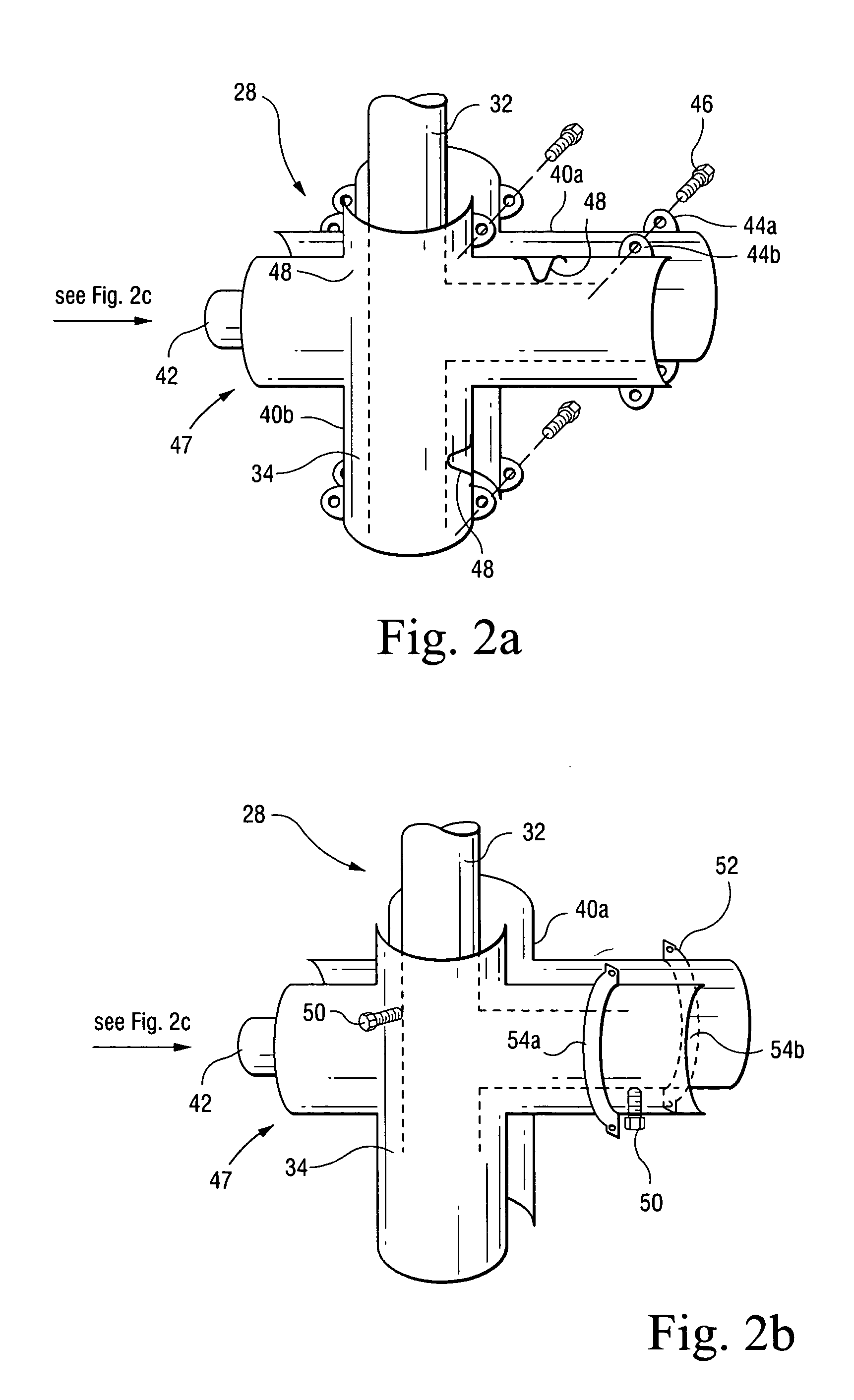
[0008] In yet another exemplary embodiment of the invention, a system for cooling at least one gas turbine liquid fuel component located in a high temperature environment to eliminate coking in the component comprises a blower to draw in external ambient air, a supply header connected to the blower, a supply manifold connected to the supply header, at least one supply tube extending from the manifold, and at least one sleeve jacketing the liquid fuel components. The sleeve includes an annulus located between the sleeve and the fuel oil components through which cooling air flows to reduce the temperature of the fuel oil components.

Problems solved by technology

This air-oil interface on the coated surfaces of the piping system and valves (e.g., check valves, ball valves, spool valves, etc.) in the presence of the radiated, conducted, and convected heat, leads to coke formation in the liquid fuel piping, resulting in flow restriction and inoperable valves.
Prior attempts have been made to direct turbine compartment cooling air flow to areas subject to coking, but sufficient temperature cooling could not be attained.

Method used


Image

  • Cooling of liquid fuel components to eliminate coking
  • Cooling of liquid fuel components to eliminate coking
  • Cooling of liquid fuel components to eliminate coking

Examples


Embodiment Construction

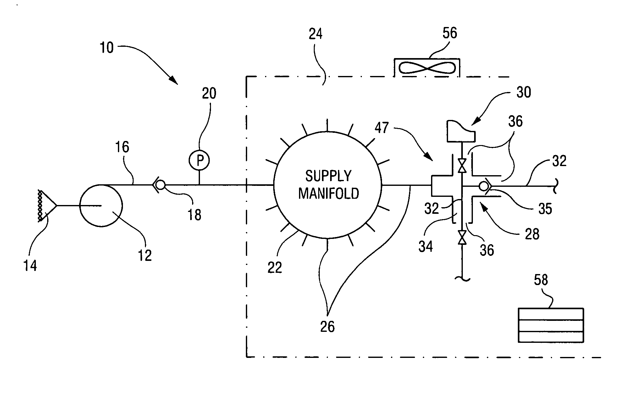
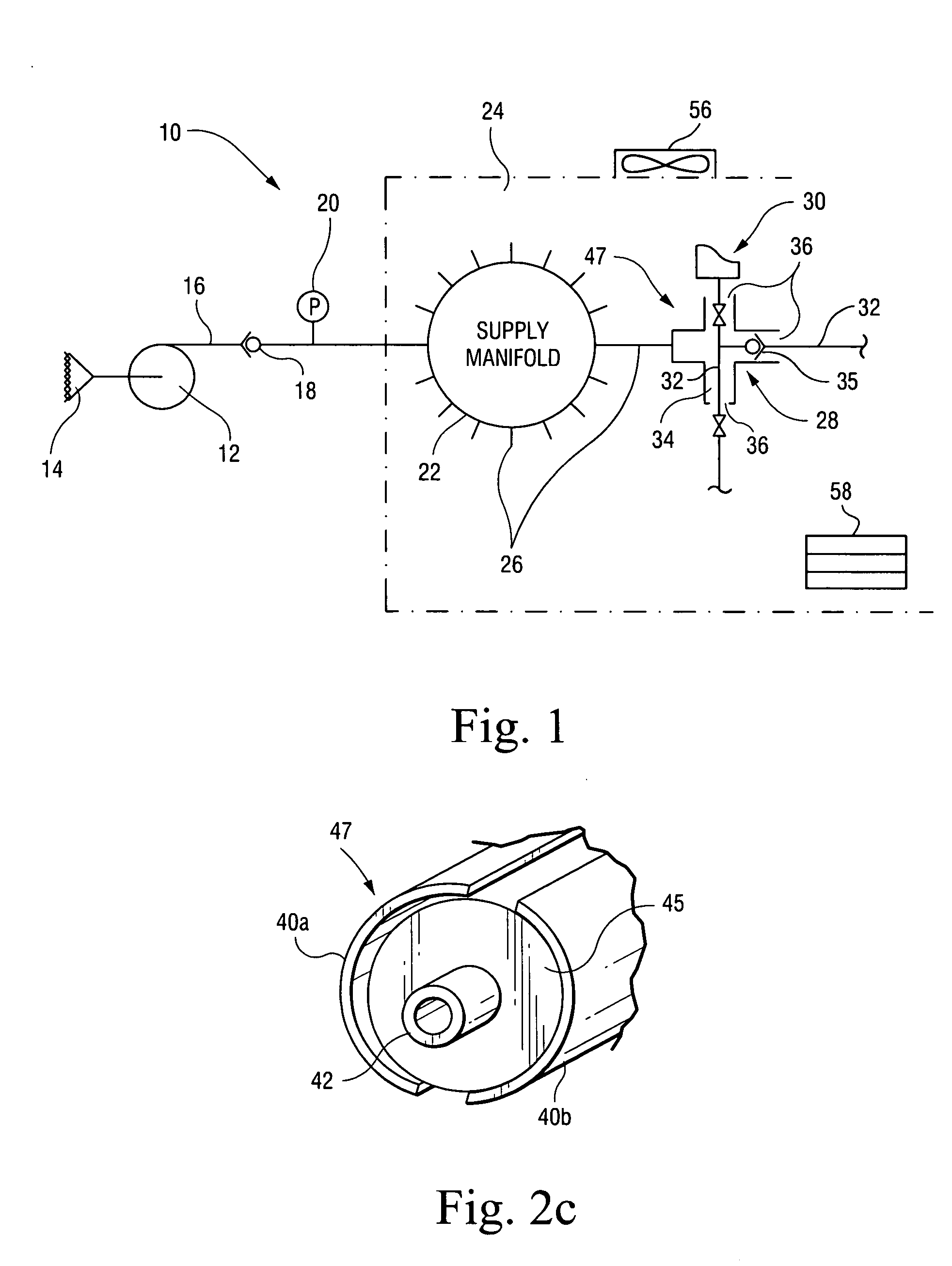
[0016]FIG. 1 illustrates an exemplary embodiment of a system, in accordance with the present invention, for eliminating coking by air cooling gas turbine liquid fuel components located in a high temperature environment. The cooling system 10 shown in FIG. 1 uses a high pressure motor driven blower 12 to draw in the required volume of cool ambient air at atmospheric conditions through a screened inlet air silencer 14 and to boost the pressure of such ambient air to overcome system resistance. The pressurized air flows through a first conduit or tube preferably in the form of a supply header 16. A backdraft damper 18 in supply header 16 prevents backflow when system 10 is not operating. A pressure switch 20 signals loss of air flow.

[0017] Supply header 16 leads to a supply manifold22 located within the turbine's enclosure 24. Extending from supply manifold 22 are a plurality of additional or second conduits preferably in the form of a plurality of individual supply tubes 26, one for ...


PUM


Abstract

A system for cooling at least one gas turbine liquid fuel component located in a high temperature environment to eliminate coking in the component is disclosed. The system includes a sleeve surrounding the liquid fuel component, a device for providing a current of cool air, and a conduit connected between the cool air device and the sleeve to direct the current of cool air into the sleeve to cool the liquid fuel component. The system can also include a manifold connected to the conduit and a plurality of second conduits for connecting the manifold to a plurality of sleeves surrounding a plurality of liquid fuel components, each sleeve being connected to a corresponding second conduit. Each sleeve includes a plurality of spacing devices for centering the sleeve around the at least one liquid fuel component so as to form an annulus between the sleeve and the liquid fuel component through which the current of cool air flows. The system can alternatively use a supply of cool liquid pumped by a pump through a conduit adjacent to a liquid fuel component to cool the component.

Description

CROSS-REFERENCES TO RELATED APPLICATIONS [0001] This application is a continuation-in-part of application Ser. No. 10 / 308,101, filed Dec. 3, 2002, the entire content of which is hereby incorporated by reference in this application.BACKGROUND OF THE INVENTION [0002] The present invention relates to a system for cooling liquid fuel components subject to conduction and radiation heating, and in particular, to a system for directing pressurized ambient temperature air to an annulus located between a component and a sleeve installed around the component or cool liquid to a tube in physical contact with the component. [0003] Gas turbines typically operate on natural gas fuel, with fuel oil (typically No. 2 distillate) often used as a contingency for periods of gas unavailability. When a gas turbine is operating on natural gas fuel, the fuel oil typically remains in liquid fuel lines (e.g., piping / tubing) leading to the combustor nozzles of the gas turbine. The stagnant fuel oil in the liq...

Claims


Application Information

Patent Timeline
Patent Type & Authority Applications(United States)
IPC IPC(8): F01D25/12F02C7/14
CPCF02C7/14F01D25/12
Inventor KAPLAN, HOWARD JAYACQUAVELLA, DAVID FRANCISJUNQUERA, STEVEN PATRICKJOHNSON, DAVID MARTINMILLER, CHRISTOPHER DAVIDIASILLO, ROBERT JOSEPHHAMPSON, GREGORY JAMESO'DELL, KEVIN JON
Owner GENERAL ELECTRIC CO
Learn More