
Fuel substance and associated cartridge for fuel cell

Inactive Publication Date: 2005-04-21
DURACELL U S OPERATIONS
View PDF7 Cites 9 Cited by
  • Summary
  • Abstract
  • Description
  • Claims
  • Application Information

AI Technical Summary

Benefits of technology

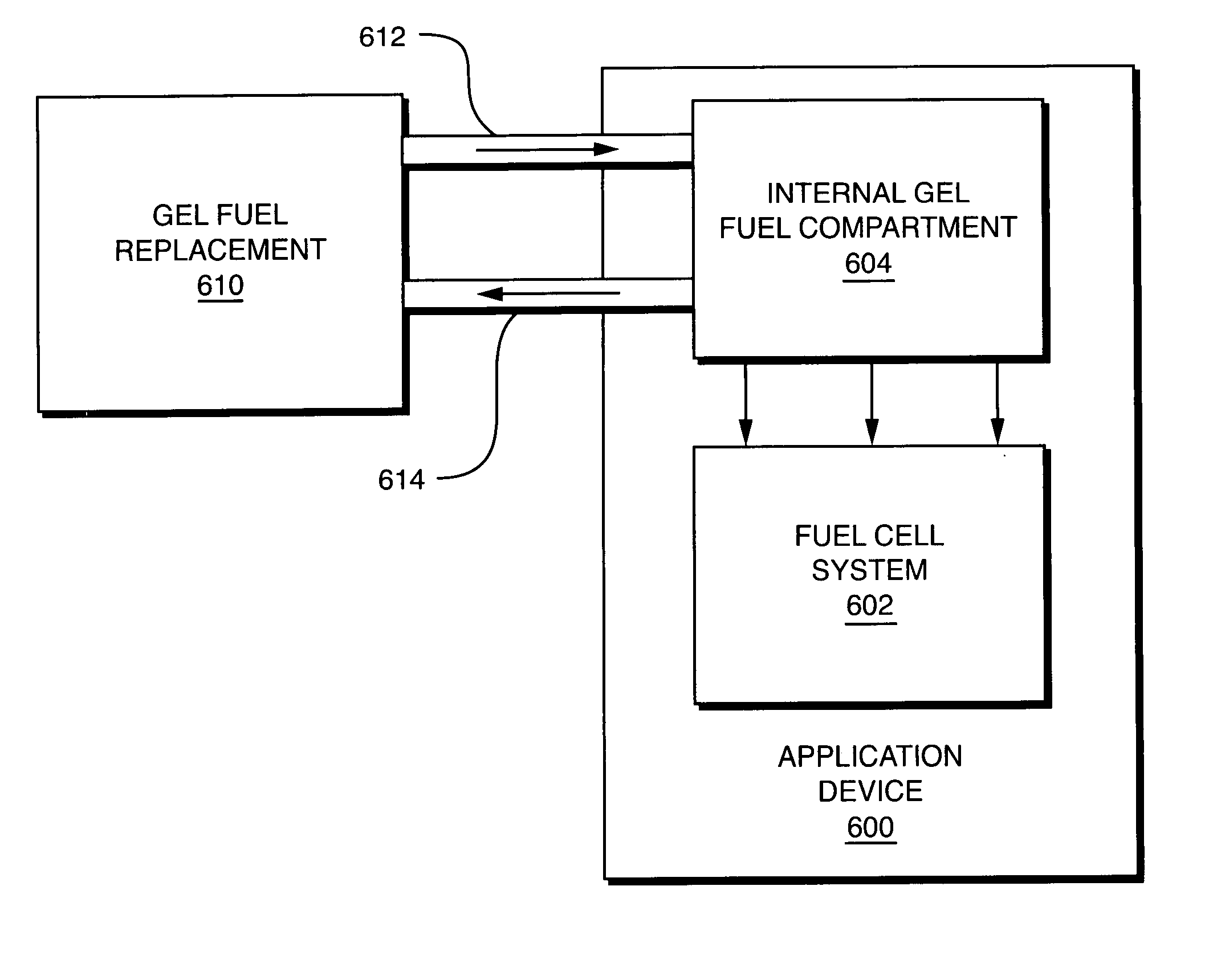
[0025] The fuel substance combined with the thickening substance, and additives, if any, together form the unique “gel fuel” of the present invention, having sufficient viscosity such that it obviates the need for complex recirculation loops, pumps and valves and other components required with most liquid fuels, and additionally minimizes undesired leakages, thus allowing a highly concentrated, vaporous fuel substance to be delivered to an associated fuel cell.
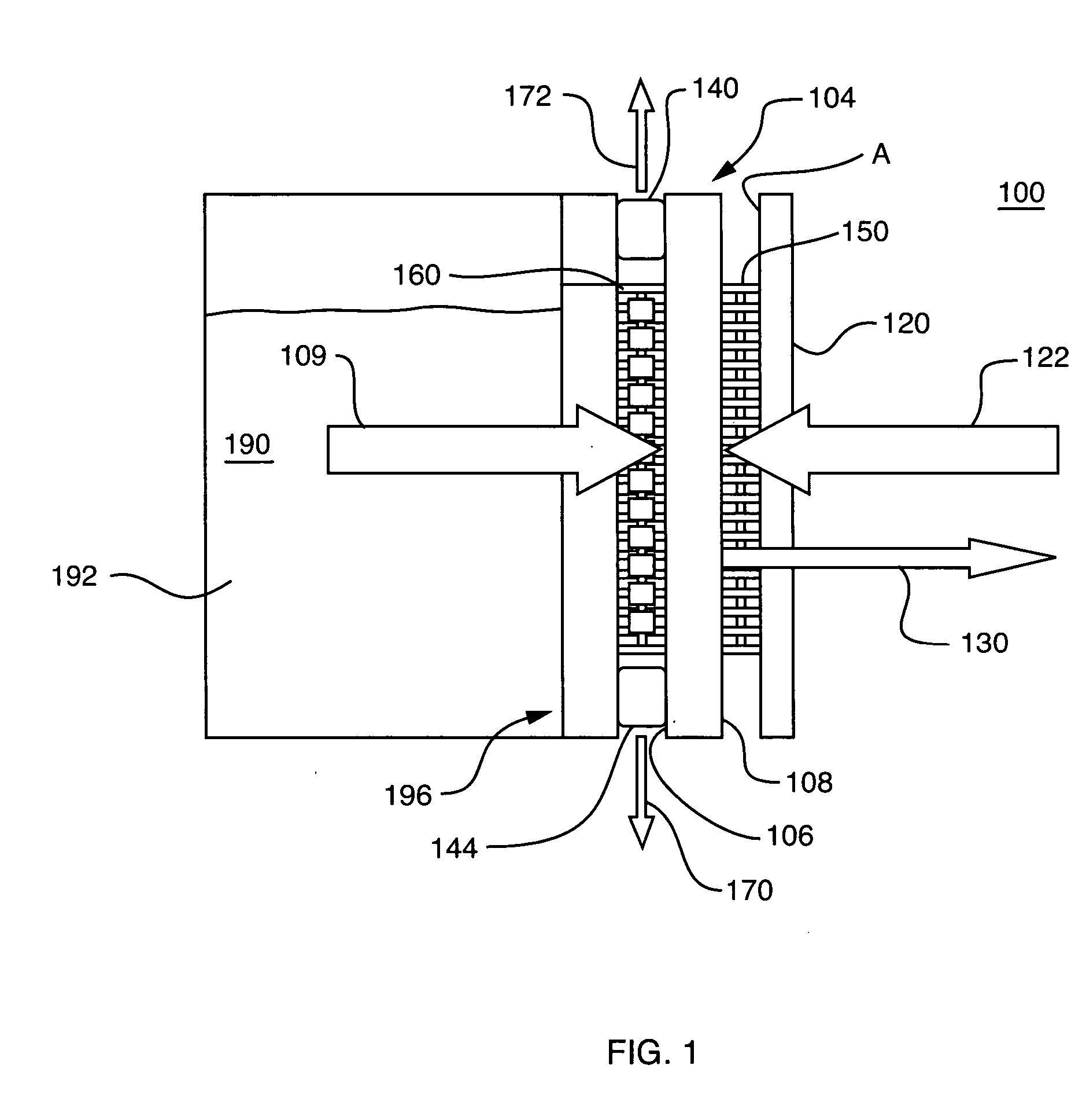
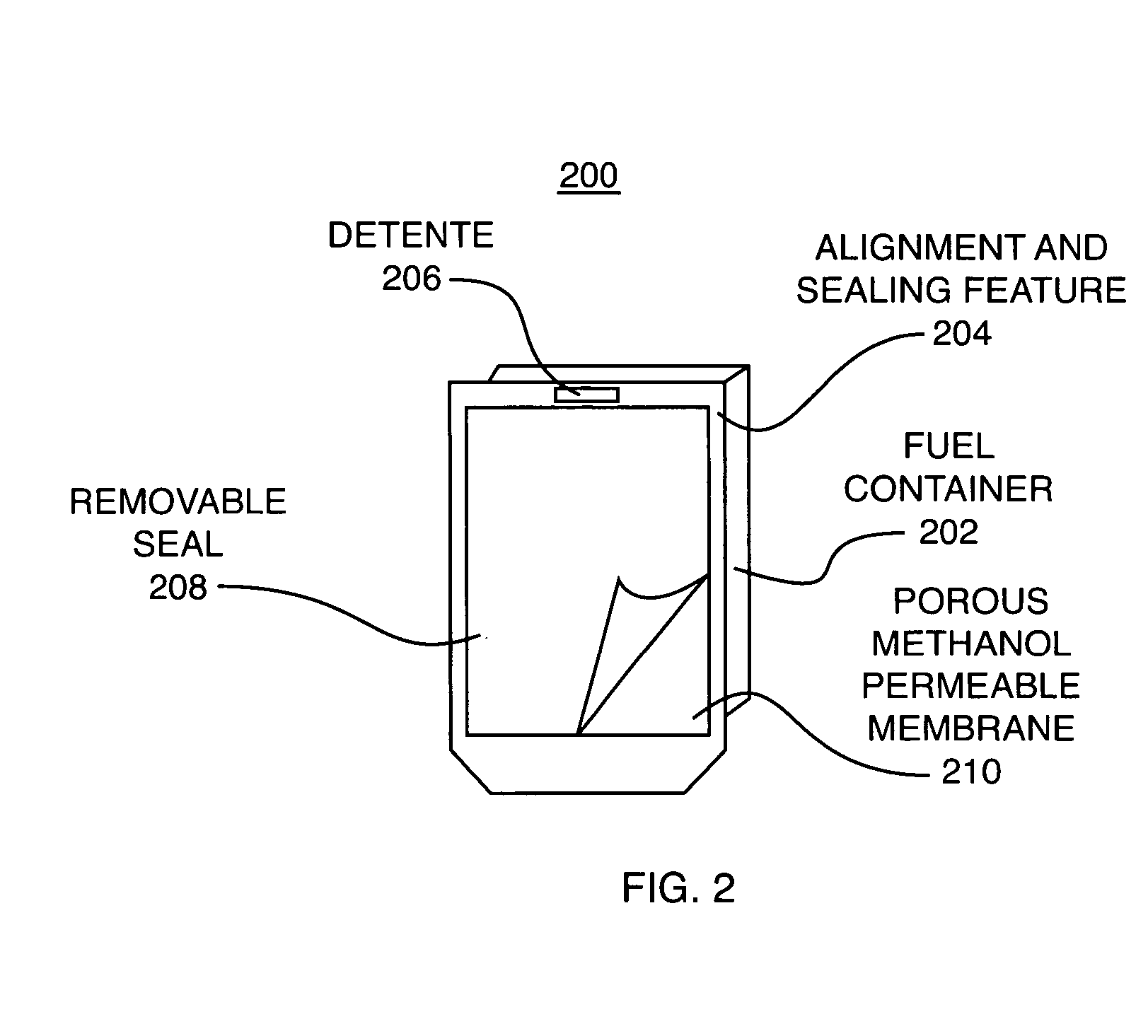
[0027] The fuel permeable membrane that is disposed upon at least a portion of the cartridge of the present invention is referred to herein as the fuel vapor-permeable layer (“FVPL”) and it may be comprised of one of a number of various alternative materials. For example, in a first embodiment of the invention, the FVPL is a monolithic layer of a material that has good selectivity between water and fuel substances, which allows the fuel substance to pass through it from the fuel cell cartridge to the anode aspect of the direct oxidation fuel cell, and substantially prevents water from travelling back into the fuel cartridge.
[0028] In accordance with another aspect of the invention, the FVPL is substantially comprised of a porous membrane, which is non-selective and allows water to pass back through the FVPL into the fuel cell cartridge. In this case, the fuel cell cartridge includes surface area increasing features that expand the overall surface area of the gel fuel that is exposed to air, even though the gel mass decreases. This enables a constant vaporous fuel delivery rate with usage and moreover, the hydrophilic gel fuel, which absorbs water, provides water management. Another functional aspect of these features is to stabilize the gel. Other embodiments include a wire mesh FVPL, or a cartridge with no FVPL

Problems solved by technology

However, because fuel processing is expensive and generally requires expensive components, which occupy significant volume, reformer-based systems are presently limited to comparatively large, high power applications.
In addition, it could lead to the generation of undesirable anode products such as formaldehyde.
However, such pervaporation membranes may need to be specially engineered, which can be costly.
In addition, such membranes, though useful for delivering the vaporous fuel, can, in time, have stability issues in which gas expansion or mass transport rates through the membrane cause deformations in the pervaporation membranes.
This can lead to additional components that may cause passive losses within the system, or can increase the cost due to the increased complexity.
However, additional recirculation loops, as well as pumps, valves and other hydraulic equipment and components for liquid management may increase the size of the overall fuel cell system.
However, even though such expansion bladders and optional force-applying elements may be desirable in some instances, in other instances they can increase the volume, complexity and weight of the fuel delivery cartridge.
Some of the disadvantages with certain liquid fuel fed systems can be addressed using a vapor fed system, such as that described in the above-cited commonly owned U.S. patent application Ser. No. 10 / 413,983, which has been incorporated herein by reference, but such systems use a liquid fuel which then undergoes a phase change when passing through a pervaporation membrane, and thus such systems still may need to carry liquid fuel in a storage tank or other container.
Another issue that arises with respect to usage of carbonaceous fuel, such as methanol, in a consumer electronic device, is that of maintaining the integrity of the cartridge so that there is no leakage of the fuel.
For example, when using a liquid fuel, a crack in the fuel cartridge may result in the fuel leaking out of the cartridge.

Method used


Image

  • Fuel substance and associated cartridge for fuel cell
  • Fuel substance and associated cartridge for fuel cell
  • Fuel substance and associated cartridge for fuel cell

Examples


example 1

[0102] The first test was conducted using the FVPL that is selective. Cell 3993 was prepared with an MEA using Nafion 1135 membrane as the polymer electrolyte. At the start of the test, a sample cup with a 5 cm2 opening area and 2 cm deep was filled with 7.4263 gram of a methanol gel. The gel composition was 1.66 wt. % Carbopol®, 0.04 wt. % NaOH and 98.3% methanol. The opening of the sample cup containing the ethanol gel was then covered with a piece of silicone membrane of 15 urn thick upported with a PVDF substrate. The sample cup thus prepared was used as the fuel artridge placed inside the cell anode compartment at the start of test. FIG. 7A is a plot 700aof the cell current during the test run of 90.6 hs. FIG. 7B shows a curve 700bof the cell temperature recorded at the cell cathode faceplate.

[0103] The decrease in cell current during the run as shown in FIG. 7Awas caused by a decrease in methanol feed rate from the gel during the run, as indicated by the decrease in the cell ...

example 2

[0107] The next example was of a system in which the porous FVPL was used. Cell 3994 was prepared similarly as cell 3993 in Example 1, except that a different membrane was used to seal the methanol gel placed inside the sample cup. At the start of the test, a sample cup with a 5 cm2 opening area and 2 cm deep was filled with 7.3025 grams of a methanol gel. The gel composition was 1.66 wt. % Carbopol®, 0.04 wt. % NaOH and 98.3 % methanol. The opening of the sample cup containing the methanol gel was then covered with a piece of Zitex A135 expanded poly tetraflouroetylene (“EPTFE”) membrane (available commercially from Norton Performance Plastics, of Wayne, N.J., USA). The A135 membrane is 5 um thick, and has a maximum functional pore size of 20-30 ums and approximate pore volume of 65 %. The sample cup thus prepared was used as the fuel cartridge placed inside the cell anode compartment at the start of test. FIG. 8 shows cell discharge current 600 recorded during the test run for the...

example 3

[0109] Cells 4011 and 4012 were prepared identically as cell 3994 described in Example 2. At the end of test, the masses of cell and fuel cartridge containing the methanol gel were measured. Methanol balance and water balance were determined based on the mass changes from the starting values, as listed in Table 3.

TABLE 3Mass balance of fuel cell test for cells 4011 and 4012Cell 4011Cell 4012Methanol in gel98.4 wt. %98.4 wt. %Gel mass at start (g)7.76487.3839Gel mass at end (g)2.14782.0075Run time (h)88.6888.64Discharge energy (Wh)9.53748.7547Energy conversion in1.131.13Wh / cc of methanolFuel efficiency88.86%92.54%Cell resistance (Ohms cm2)0.2870.357Average rate of water16.915.6generation (mg / g cm2)Average rate of water removal14.313.7at cathode (mg / g cm2)

[0110] Example 4

[0111] Cell 4035 was prepared similarly as cell 3993 described in Example 1, except that the polymer electrolyte membrane used was a Nafion 112 membrane. At the start of the test, a sample cup with a 5 cm2 opening ...


PUM


Abstract

The present invention provides a gel fuel, which includes a fuel substance held in a polymeric structure. One embodiment of the composition includes neat methanol, to which a thickening substance, such as that sold commercially under the trade name Carbopol®, is added to impart viscosity, as well as stabilizing and suspending properties. In addition to the thickening substance, a further substance can be added to balance the pH of the gel fuel when needed. In accordance with the invention, a fuel cell cartridge is provided that has at least one aspect that is methanol-permeable, and which may include a fuel vapor permeable layer and it may be comprised of one of a number of various alternative materials. Features within the fuel cartridge can be used to increase surface area of the gel fuel, and to maintain the gel fuel in a desired location within the cartridge.

Description

BACKGROUND OF THE INVENTION [0001] 1. Field of the Invention [0002] This invention relates generally to direct oxidation fuel cells, and more particularly, to fuel substances and cartridges for use in supplying fuel substances to such fuel cells. [0003] 2. Background Information [0004] Fuel cells are devices in which electrochemical reactions are used to generate electricity. A variety of materials may be suited for use as a fuel depending upon the materials chosen for the components of the cell. Organic materials, such as methanol or natural gas, are attractive fuel choices due to the their high specific energy. [0005] Fuel cell systems may be divided into “reformer-based” systems (i.e., those in which the fuel is processed in some fashion to extract hydrogen from the fuel before it is introduced into the fuel cell system) or “direct oxidation” systems in which the fuel is fed directly into the cell without the need for separate internal or external processing. Most currently avail...

Claims


Application Information

Patent Timeline
IPC IPC(8): C10L7/04H01M8/04H01M8/10
CPCC10L7/04H01M8/04082Y02E60/523H01M8/1009H01M8/1011H01M8/04208Y10T137/86276Y02E60/50
Inventor BECERRA, JUAN J.KOVACS, FRANK W.REN, XIAOMING
Owner DURACELL U S OPERATIONS
Learn More