Millimeter wave surface mount filter

Inactive Publication Date: 2005-04-28
REVEAL IMAGING
View PDF25 Cites 21 Cited by
  • Summary
  • Abstract
  • Description
  • Claims
  • Application Information

AI Technical Summary

Benefits of technology

[0009] It is therefore an object of the present invention to provide a millimet

Problems solved by technology

These filters are expensive, typically $10 each at the present time, and are usually hand-tuned during fabrication.
Conventionally designed parallel, coupled line filters are not practical at

Method used


Image

  • Millimeter wave surface mount filter
  • Millimeter wave surface mount filter
  • Millimeter wave surface mount filter

Examples


Embodiment Construction

[0024] The present invention will now be described more fully hereinafter with reference to the accompanying drawings, in which preferred embodiments of the invention are shown. This invention may, however, be embodied in many different forms and should not be construed as limited to the embodiments set forth herein. Rather, these embodiments are provided so that this disclosure will be thorough and complete, and will fully convey the scope of the invention to those skilled in the art. Like numbers refer to like elements throughout.

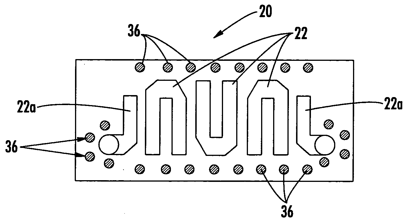
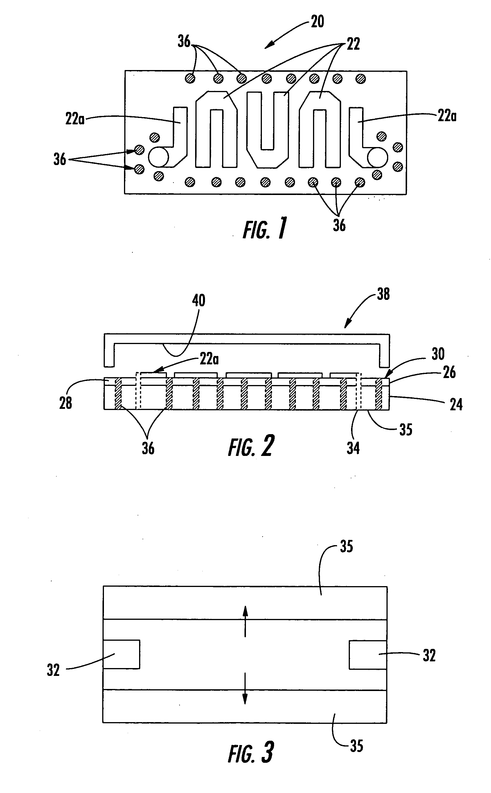
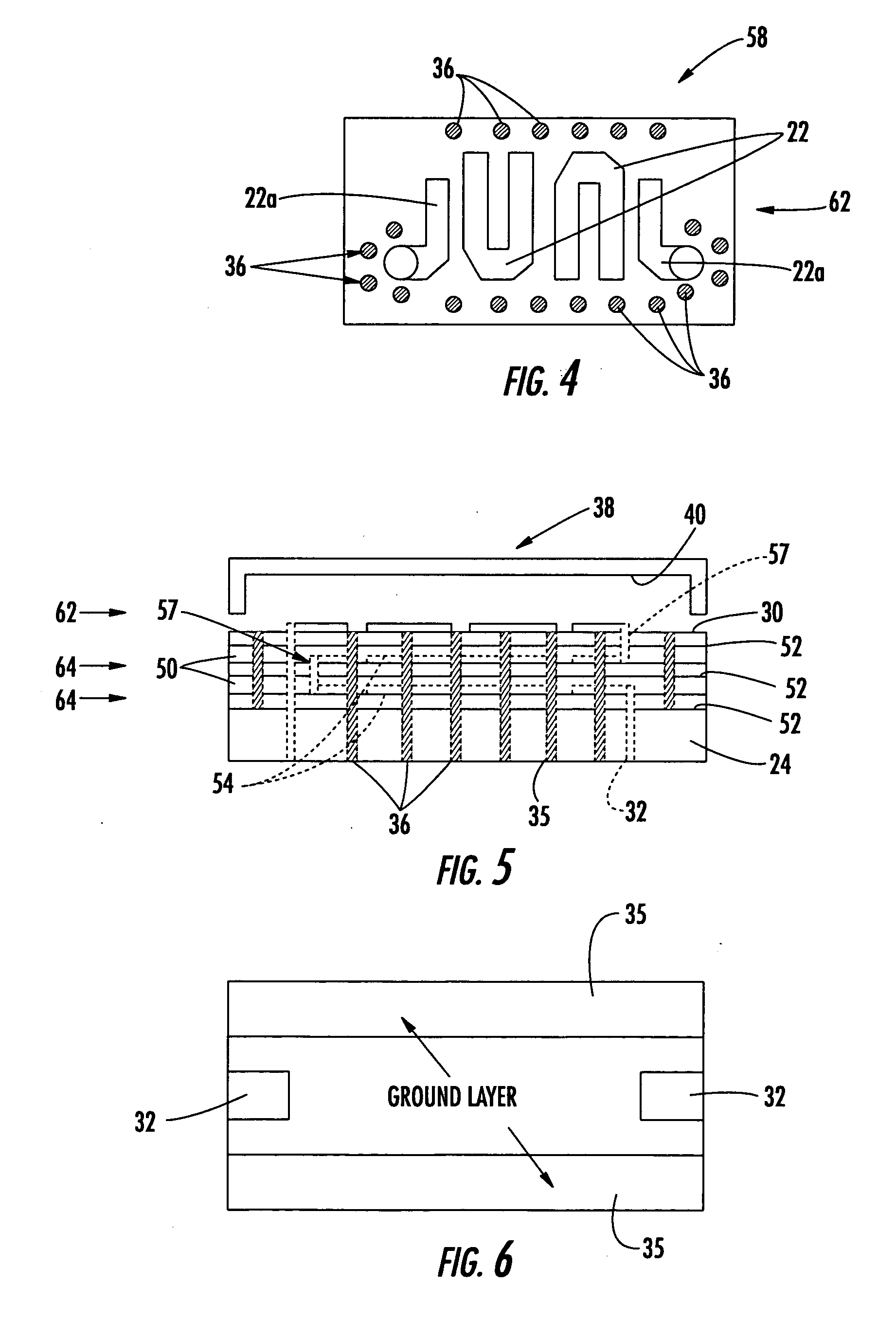
[0025] The present invention advantageously provides a small, low cost, high performance, millimeter wave RF filter using standard thick film technology and manufacturing tolerances. The high performance filter of the present invention is designed with unique hairpin resonators that are folded upon themselves and manufactured on ceramic material, such as LTCC. No other packaging is required. It achieves high RF performance using standard thick film techn...


PUM


Abstract

A millimeter wave filter for surface mount applications includes at least one low temperature, co-fired ceramic layer defining an outer filter surface. A plurality of parallel, coupled line millimeter wavelength hairpin resonators, each formed from a single stripline or microstrip, are positioned on the outer filter surface. Each hairpin resonator is folded back upon itself into substantially parallel resonator lines.

Description

FIELD OF THE INVENTION [0001] This invention relates to the field of millimeter wave filters, and more particularly, this invention relates to millimeter wave filters, such as parallel coupled line filters formed as hairpin filters. BACKGROUND OF THE INVENTION [0002] Almost every high frequency, RF module manufactured today requires a number of filters, including millimeter wave filters. For example, a transceiver will typically have an image reject filter and one local oscillator (LO) reject filter. The estimated number of RF modules built worldwide, including cell phones, is now over 600 million. [0003] Traditionally, high performance filters at frequencies greater than 800 MHz for use in millimeter wavelength applications are designed and fabricated using dielectric resonators. Tight design and manufacturing tolerances are required to achieve a desired filter response at these high frequencies. The filter length and width usually varies as a function of frequency band, substrate ...

Claims


Application Information

Patent Timeline
IPC IPC(8): H01P1/203
CPCH01P1/20381H01P1/20336
Inventor FISCHER, EUGENE
Owner REVEAL IMAGING
Why Eureka
Try Eureka