Method and apparatus for measuring gas transmission rates of deformable or brittle materials

a technology of brittle materials and gas transmission rates, which is applied in the field of apparatus and methods for measuring the transmission rate and nano leakage of gas, and can solve problems such as false positives, failure of mass spectrometers to operate in high-vacuum systems, and failure to detect false positives

Active Publication Date: 2005-05-05
MODERN CONTROLS
View PDF7 Cites 51 Cited by
  • Summary
  • Abstract
  • Description
  • Claims
  • Application Information

AI Technical Summary

Benefits of technology

[0015] The foregoing and other objects and advantages will become apparent from the following specification and claims and with reference to the appended drawings.

Problems solved by technology

This results in very precise, accurate measurements of the gas that would otherwise not be possible.
One drawback of this method, especially when measuring the gas transmission rate of deformable and brittle materials, is that mass spectrometers operate in high-vacuum systems, as noted previously.
When measuring the gas transmission rates of deformable and / or brittle test materials, the exposure of the test material to vacuum conditions may result in false positives, or in other words transmission rates and nanoleaks (caused by flexing of materials) in excess of actual values.
Further, if the test material is brittle, as in the case of certain epoxies, direct exposure to high-vacuum conditions may cause the test material to fracture.
The brittle epoxy may fracture and / or delaminate from the metal plate as a result of the high-vacuum conditions in the upper test chamber.
This phenomena causes leakage of the test gas through the fractures and around the junctures where delamination occurs, which in turn results in transmission rates in excess of the actual gas transmission rate of the test epoxy material.

Method used


Image

  • Method and apparatus for measuring gas transmission rates of deformable or brittle materials
  • Method and apparatus for measuring gas transmission rates of deformable or brittle materials
  • Method and apparatus for measuring gas transmission rates of deformable or brittle materials

Examples


Embodiment Construction

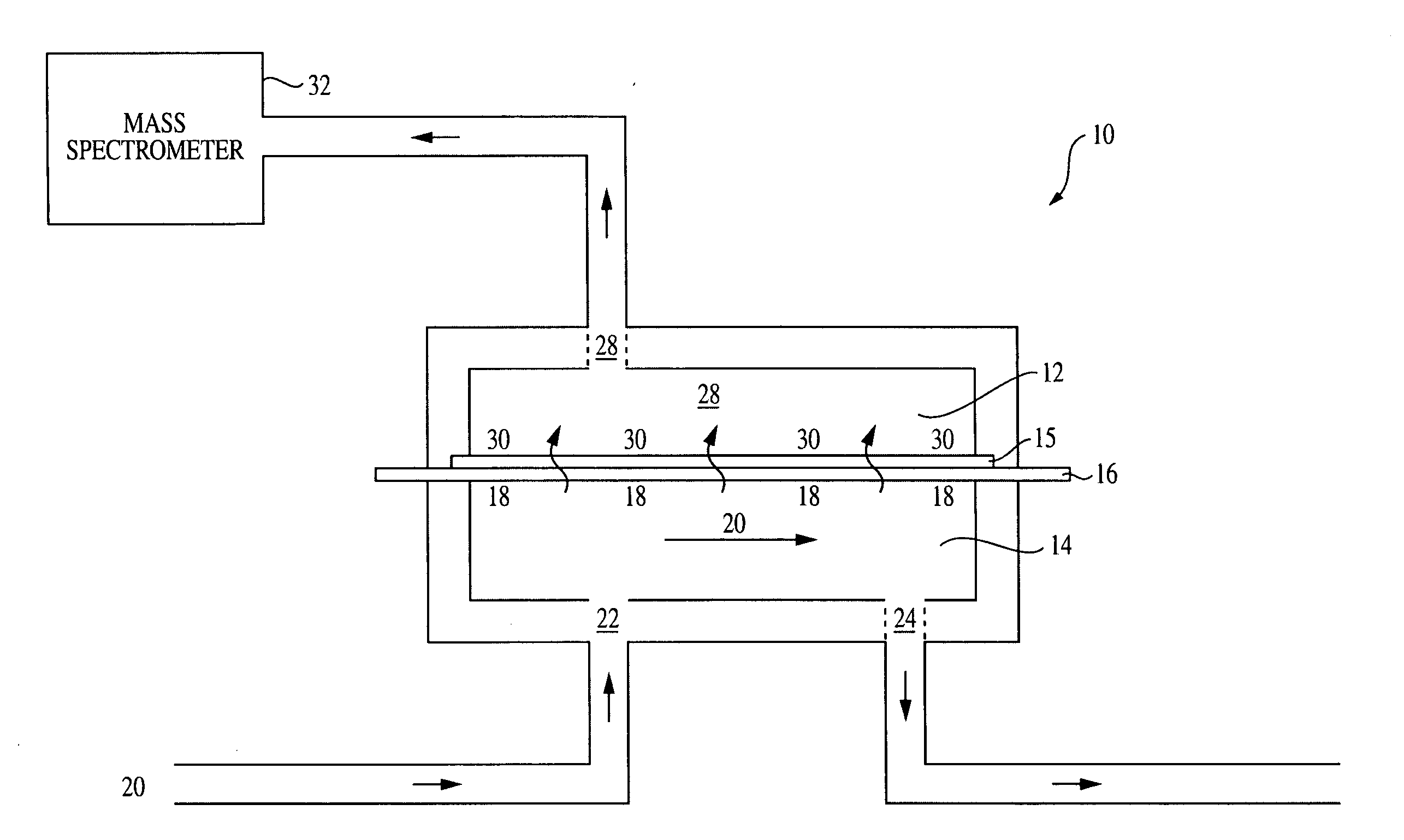
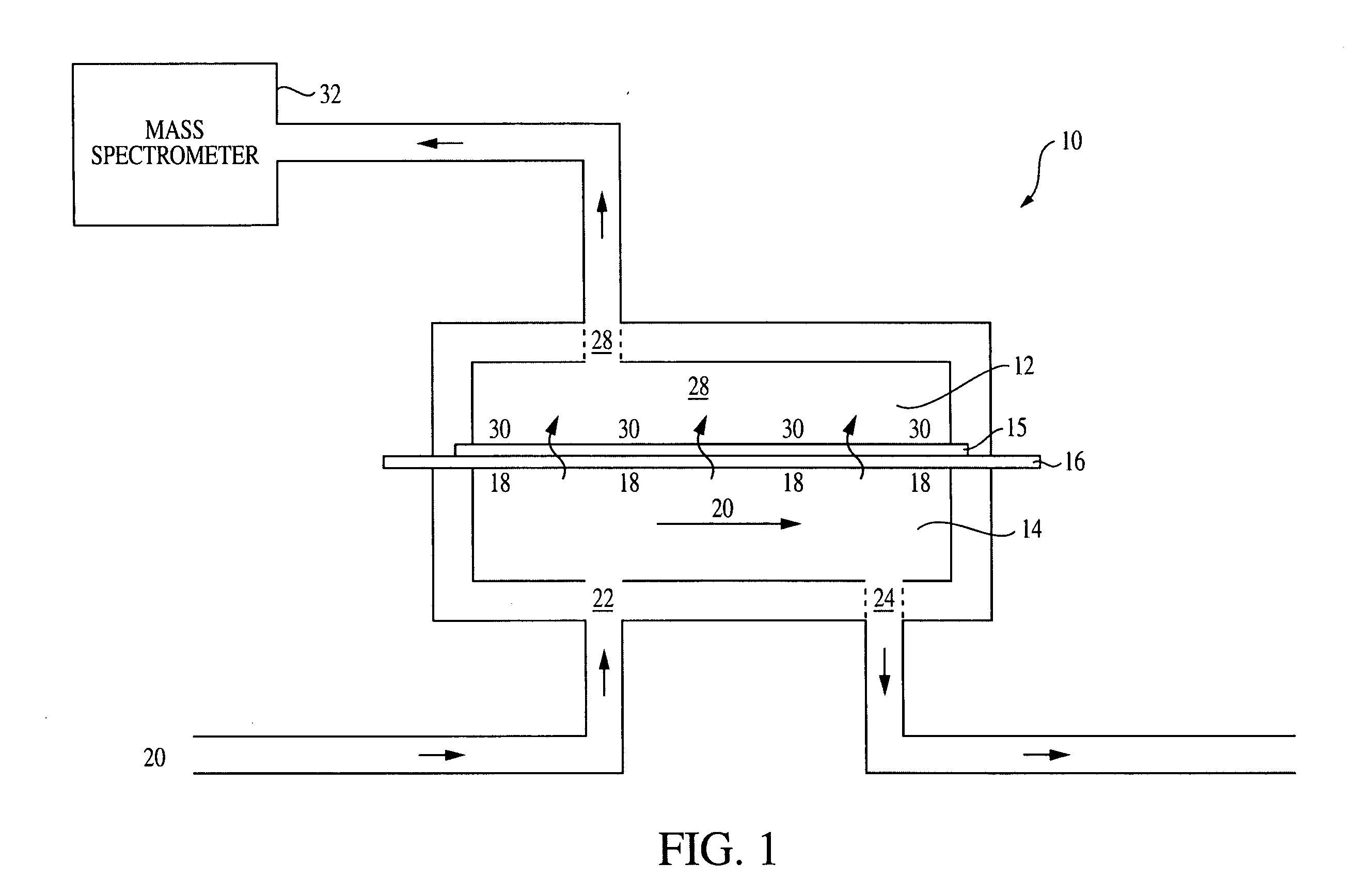
[0021]FIG. 1 illustrates the test setup for conducting the first step of the method in accordance with the present invention. A test chamber 10 includes an upper diffusion cell 12 and a lower diffusion cell 14. A guard material 16 is positioned on top of the lower diffusion cell 14 and a support grid 15 is positioned on top of the guard material. The upper and lower diffusion cells 12 and 14 are then clamped together with support grid 15 and guard material 16 therebetween. It is desirable, but not essential, for the guard material 16 to have a certain rigidity so that it does not deform under the high-vacuum system of the mass spectrometer but the guard material should not be so rigid or brittle that it fractures. Polyester materials such as polyethylene terephthalate (e.g. Mylar® available from Dupont, Wilmington, Del.); polystyrenes such as acrylonitrile butadiene styrene; and polycarbonate materials such as GE Plastics™ and Lexan® may be used. In the alternative, it is not essent...


PUM

PropertyMeasurementUnit
thicknessaaaaaaaaaa
gas transmission rateaaaaaaaaaa
mass spectrometeraaaaaaaaaa

Abstract

Provided are an apparatus and a method for measuring gas transmission rates and nanoleaks of deformable and brittle materials. The apparatus includes a test chamber having an upper and lower diffusion cells that when closed form a chamber wall seal, a gas inlet and a gas outlet in fluid communication with the lower diffusion cell, the upper diffusion cell being fluidly connected to a high-vacuum mass spectrometer. The method of measuring gas transmission rates and nanoleaks includes placing a sealed package containing the test gas in the lower diffusion cell, closing the upper and lower diffusion cells, flushing the lower diffusion cell with a source of a second gas other than the test gas, closing off the source of the second gas; and measuring the leak rate of the sealed package.

Description

BACKGROUND OF THE INVENTION [0001] 1. Field of the Invention [0002] The present invention relates to an apparatus and method for measuring the transmission rate and nanoleaks of a gas through a test material. In particular, the invention relates to an apparatus and method for measuring the gas transmission rates of brittle and deformable materials. [0003] 2. Description of the Related Art [0004] Mass spectrometers use the difference in mass-to-charge ratio (m / e) of ionized atoms or molecules to separate them from each other. Mass spectrometry is therefore useful for quantitation of atoms or molecules and also for determining chemical and structural information about molecules. The general operation of a mass spectrometer is (i) create gas-phase ions; (ii) separate the ions in space or time based on their mass-to-charge ratio; and (iii) measure the quantity of ions of each mass-to-charge ratio. In general a mass spectrometer consists of an ion source, a mass-selective analyzer, and a...

Claims


Application Information

Patent Timeline
Patent Type & Authority Applications(United States)
IPC IPC(8): G01N7/10G01N15/08
CPCG01N7/10H01J49/0427H01J49/0027G01N15/0826
Inventor ASCHEMAN, TIMOTHY ALANMAYER, DANIEL W.
Owner MODERN CONTROLS
Why Eureka
Try Eureka