Distributed oscillator architectures

a technology of distributed oscillators and architectures, applied in the field of oscillators, can solve the problems of insufficient high frequency oscillator in many respects, difficult to achieve a wide tuning range and good phase noise performance, and further exacerbate the problem of high frequency oscillator problems. achieve the effect of better performan

Inactive Publication Date: 2005-05-05
HAJIMIRI SEYED ALI +1
View PDF3 Cites 10 Cited by
  • Summary
  • Abstract
  • Description
  • Claims
  • Application Information

AI Technical Summary

Benefits of technology

[0007] In particular, a distributed oscillator includes a core structure, namely, a traveling-wave amplification section (TWAS). A TWAS has four ports, such as would be formed by a first transmission line between the first two ports, a second transmission line between the last two ports, and amplification devices between the two transmission lines. An input signal enters the first port of a TWAS and travels down to its second port. The input signal is also amplified and the amplified signa

Problems solved by technology

Furthermore, existing lumped solutions for integrated, high frequency oscillators are inadequate in many regards.
For example, while it is possible to design an LC oscillator on a silicon substrate at up to 10 GHz, it is difficult to achieve a wide tuning range and good phase noise performance.
The problem is further exacerbated as the operation frequency increases—as the operation frequency approaches the cut-off frequency of the transistors, it is even difficult to achieve the oscillation at all.
In addition, distributed oscillators provide a low-cost system-on-a-chip solution for mobile phone handsets, wireless LAN products, and other applications where low-speed mainstream CMOS processes are preferred and thus LC oscillators or other prior art oscillators become unsuitable.
Despite the earlier advances, the full potential of distributed oscillators has yet to be exploited.
However, the conventional distributed oscillator architecture compromises its phase noise performance because of tha

Method used


Image

  • Distributed oscillator architectures
  • Distributed oscillator architectures
  • Distributed oscillator architectures

Examples


Embodiment Construction

[0015] The invention summarized above and defined by the enumerated claims may be better understood by referring to the following detailed description, which should be read in conjunction with the accompanying drawings. This detailed description of particular preferred and exemplary embodiments, set out below to enable one to build and use particular implementations of the invention, is not intended to limit the enumerated claims, but to serve only as particular examples thereof. The particular examples set out below are the preferred specific implementations of integrated distributed oscillators. Prior to describing the invention, some background on the operation of integrated distributed oscillators will be illustrative.

II. Conventional Distributed Oscillators

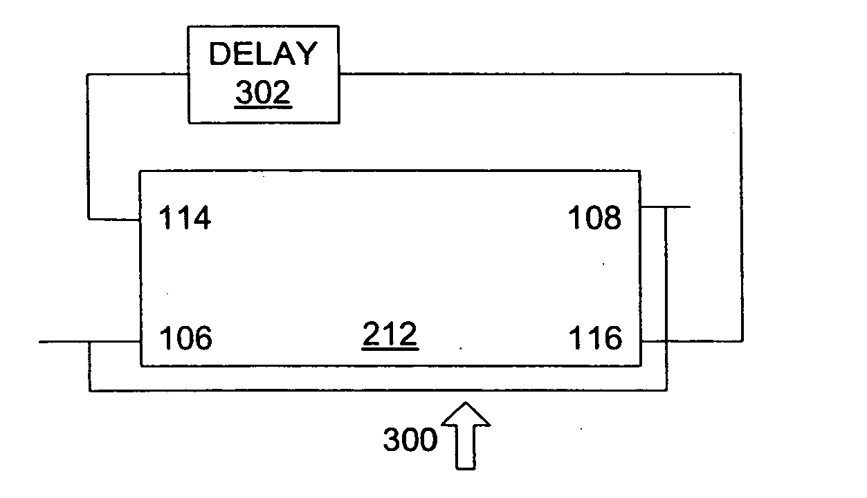
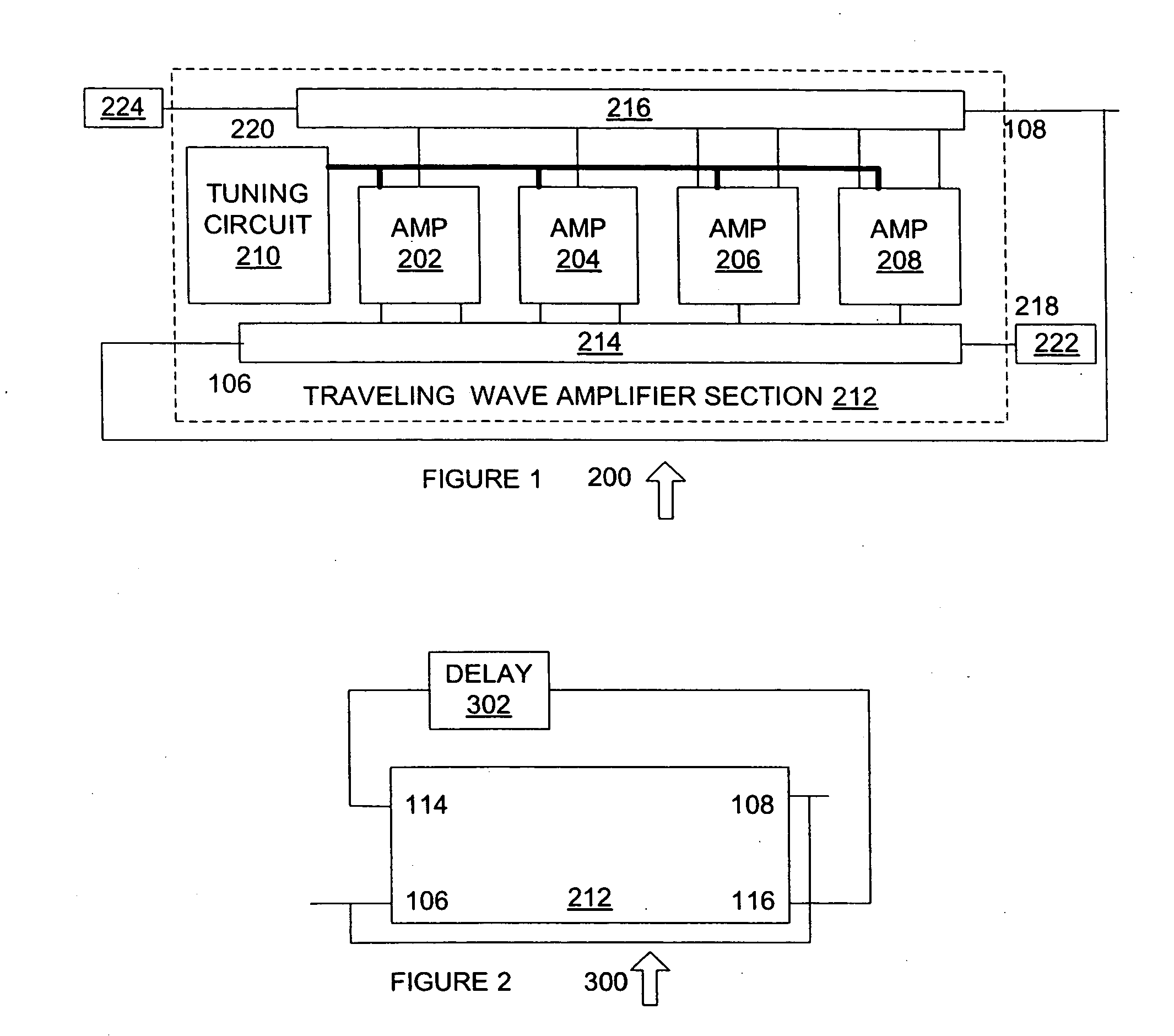
[0016]FIG. 1 is a diagram of a conventional distributed oscillator 200, which includes traveling-wave amplifier section (TWAS) 212. TWAS 212 is adapted to be used in conjunction with FIGS. 2 through 6A, as described furthe...


PUM


Abstract

A voltage controlled oscillator is provided. The voltage controlled oscillator includes a traveling-wave amplifier having two inputs and two outputs, such as would be formed by a first transmission line having a first input and a first output and a second transmission line having a second input and a second output. The first output of the traveling-wave amplifier is connected to the first input. A delay is connected between the second output and the second input, so as to provide a voltage controlled oscillator that requires minimal power to operate.

Description

FEDERAL SUPPORT STATEMENT [0001] The U.S. Government has a paid-up license in this invention and the right in limited circumstances to require the patent owner to license others on reasonable terms as provided for by the terms of ECS-0083220 awarded by NSF.FIELD OF THE INVENTION [0002] The present invention relates generally to the field of oscillators and more particularly to distributed oscillators (tunable or not tunable), including distributed voltage-controlled oscillators (DVCO's), which are tunable distributed oscillators tuned by a control signal. BACKGROUND OF THE INVENTION [0003] Oscillators are essential building blocks in modern communication systems and other applications. A distributed oscillator can operate at frequencies close to or beyond the cut-off frequency of transistors, which allows them to be used in extremely high frequency applications, such as proposed broadband wireless communications at 60 GHz or fiber-optic communication systems at 40 Gb / s and beyond. F...

Claims


Application Information

Patent Timeline
IPC IPC(8): H03B5/18
CPCH03B5/1852H03B5/1847
Inventor HAJIMIRI, SEYED-ALIWU, HUI
Owner HAJIMIRI SEYED ALI
Why Eureka
Try Eureka