Ask demodulation device and wireless device using the same

a demodulation device and wireless technology, applied in the field of ask demodulation device and wireless device using the same, can solve the problems of slow response of mean value, limited change of threshold value quickly, and bit errors often occurring in manchester code decoding, etc., to achieve increase snr, and excellent bit error rate characteristics

Active Publication Date: 2005-05-05
PANASONIC INTELLECTUAL PROPERTY CORP OF AMERICA
View PDF5 Cites 20 Cited by
  • Summary
  • Abstract
  • Description
  • Claims
  • Application Information

AI Technical Summary

Benefits of technology

[0039] Also, it is possible to remove a high frequency component by connecting the low-pass filter to a previous or following stage of the data extraction section. As a result, it is possible to increase SNR and provide excellent bit error rate characteristics.
[0040] By using the integration filter as a low-pass filter and setting the integration period to less than one bit time, it is possible to prevent an NRZ data component from being removed. As a result, it is possible to obtain more excellent bit error rate characteristics. By setting the integration period to 0.5 bit time, a correlation receiver for obtaining a correlation between a detected signal and a rectangular signal can be structured by the data extraction section and the integration filter. As a result, bit error rate characteristics are improved. Also, the clock extraction section is less subject to noise at the time of detection of crossing points.
[0041] Furthermore, by generating a frame data so that a pattern “101” or “0

Problems solved by technology

However, too long time period for obtaining a mean value slows a response.
Thus, bit errors often occur when Manchester code is decoded.
Thus, the method as disclosed in patent document 2 has limitations in changing the threshold value quickly enough to deal with a case where a packet is received or the level of the detected signal is varied, for example.
As such, the conventional ASK demodulation device adopting the method of comparing a detected signal with a threshold value for determini

Method used


Image

  • Ask demodulation device and wireless device using the same
  • Ask demodulation device and wireless device using the same
  • Ask demodulation device and wireless device using the same

Examples


first embodiment

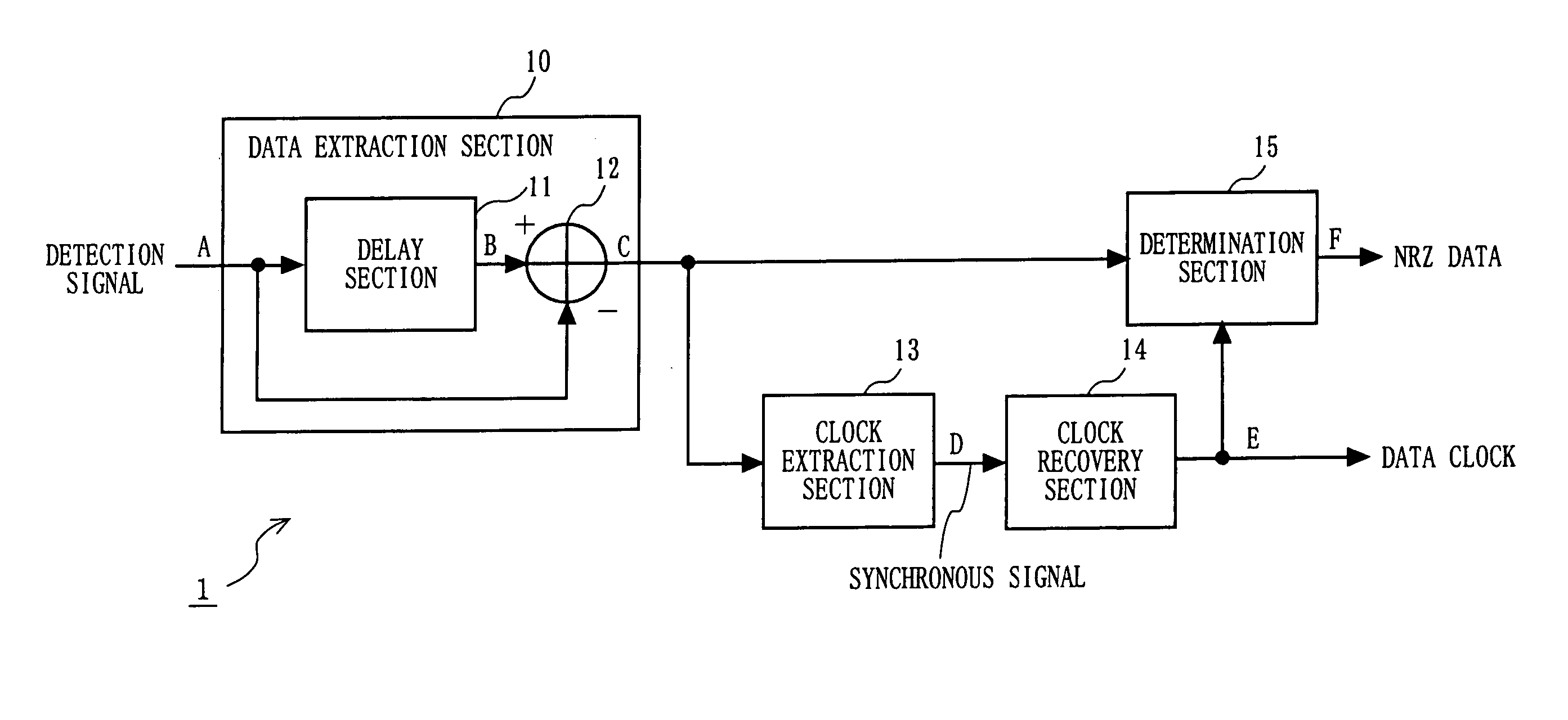
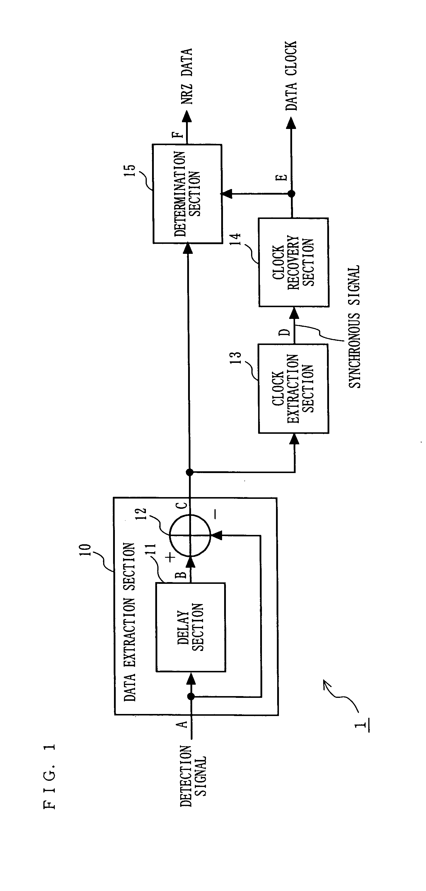
[0083]FIG. 1 is a block diagram illustrating a structure of an ASK demodulation device 1 according to a first embodiment of the present invention. In FIG. 1, the ASK demodulation device 1 includes a data extraction section 10, a clock extraction section 13, a clock recovery section 14, and a determination section 15. The data extraction section 10 includes a delay section 11 and a subtraction section 12.

[0084] A detection section (not shown) detects a modulated signal which is ASK-modulated with a Manchester-encoded data sequence (Manchester data) by using a method such as synchronous detection or asynchronous detection, and inputs the detected signal to the data extraction section 10.

[0085] The data extraction section 10 outputs a signal including information (hereinafter referred to as an NRZ data component) about pre-Manchester-encoded NRZ data.

[0086] The clock extraction section 13 extracts, from the output signal of the data extraction section 10, a component (hereinafter re...

second embodiment

[0123]FIG. 14 is a block diagram showing a structure of an ASK demodulation device 2 according to a second embodiment of the present invention. In FIG. 14, the ASK demodulation device 2 includes the data extraction section 10, an integration filter 30, the clock extraction section 13, the clock recovery section 14, and the determination section 15. In FIG. 14, any component elements function similarly to their counterparts in the ASK demodulation device 1 as shown in FIG. 1 according to the first embodiment will be denoted by the same reference numerals as those used therein, and the description thereof is omitted.

[0124] A detected signal obtained by detecting a modulated signal which is ASK-modulated with a Manchester-encoded data sequence by using a method such as synchronous detection or asynchronous detection is inputted to the ASK demodulation device 2. The detected signal inputted to the ASK demodulation device 2 is inputted to the data extraction section 10. The data extract...

third embodiment

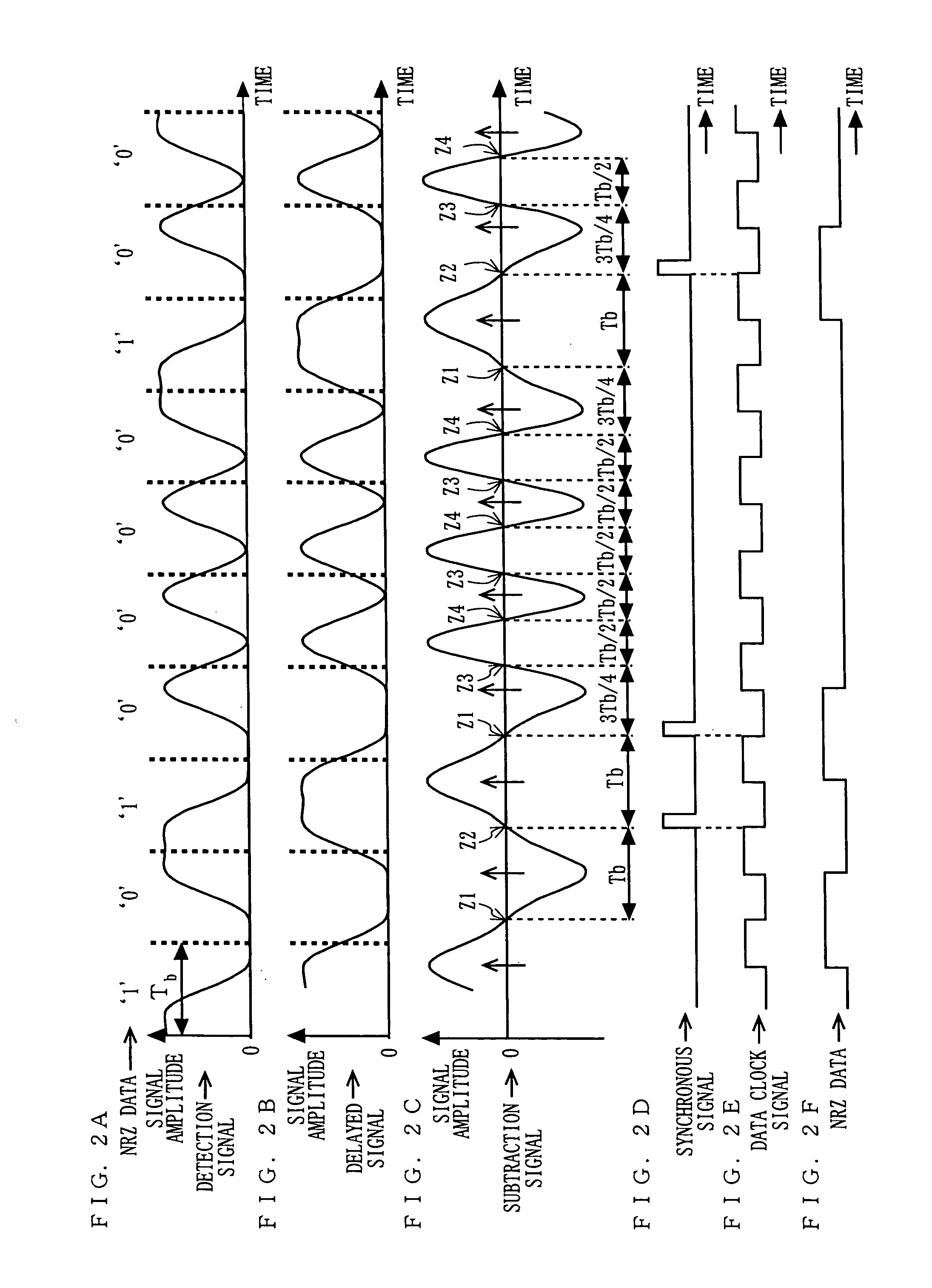
[0157] The ASK demodulation devices 1 and 2 according to the first and second embodiments, respectively, obtain NRZ data whose bit error rate is low by adjusting a data clock signal utilizing the fact that the zero-crossing time interval of the output signal of the data extraction section 10 is Tb when an NRZ data pattern “101” or “010” is received. In a third embodiment, a signal is transmitted and received using a frame data including at least one NRZ data pattern “101” or “010”.

[0158]FIG. 19 is a block diagram showing a structure of a wireless system and a wireless device 3 according to a third embodiment of the present invention. In the wireless system as shown in FIG. 19, a modulated signal is transmitted and received between the wireless devices 3 and 4, whereby wireless communication is performed. Note that only two wireless devices are shown in FIG. 19, but three or more wireless devices may be included.

[0159] In FIG. 19, the internal structures of the wireless devices 3 a...


PUM


Abstract

A delay section delays a detected signal by less than one bit time in NRZ data. A subtraction section performs subtraction between a delayed signal and the detected signal, and outputs a resultant signal. A clock extraction section extracts, from crossing points of a subtracted signal, crossing points whose time interval is more than or equal to Tb-α and less than or equal to Tb+β (0<α≦Tb/8, 0<β≦Tb: Tb is one bit time in the NRZ data), and outputs a synchronous signal synchronized with the extracted crossing point. A clock recovery section synchronizes a clock signal with the phase of the synchronous signal, and outputs a data clock signal. A determination section determines the polarity of the subtracted signal outputted from the subtraction section in accordance with the data clock signal, and outputs the determination result as NRZ data.

Description

BACKGROUND OF THE INVENTION [0001] 1. Field of the Invention [0002] The present invention relates to a demodulation device for demodulating a signal modulated with a data sequence encoded by using a predetermined scheme and a wireless device using the same demodulation device. More particularly, the present invention relates to an ASK (Amplitude Shift Keying) demodulation device for demodulating a signal (hereinafter referred to as a modulated signal) obtained by modulating a carrier which is ASK-modulated with a data sequence (Manchester data) obtained by Manchester-encoding NRZ (Non Return Zero) data, and a wireless device using the ASK demodulation device. [0003] 2. Description of the Background Art [0004] Manchester encoding is a scheme of encoding data in which NRZ data “0” is mapped to “01” and NRZ data “1” is mapped to “10”. As such, in Manchester encoding, one bit is translated into a two-bit code. Thus, there is always a level transition in the middle of each bit time of Ma...

Claims


Application Information

Patent Timeline
IPC IPC(8): H03M5/12H04L27/02H04L25/49H04L27/06
CPCH04L27/06H04L25/4904H04L27/02H03M5/12
Inventor MIYANAGA, KENJIKIMURA, TOMOHIROMORI, KENICHITAKAI, HITOSHI
Owner PANASONIC INTELLECTUAL PROPERTY CORP OF AMERICA
Why Eureka
Try Eureka