Scanning device with a positioning sensor and a corresponding processing method to obtain images

a scanning device and positioning sensor technology, applied in the field of optical scanning technology, can solve the problems of large volume, heavy weight, inconvenient scanning of all images of a book, etc., and achieve the effects of reducing data transmission, simple structure, and low cos

Inactive Publication Date: 2005-05-05
SHENZHEN SYSCAN TECHC CO LTD
View PDF5 Cites 7 Cited by
  • Summary
  • Abstract
  • Description
  • Claims
  • Application Information

AI Technical Summary

Benefits of technology

[0006] Since a scanning device with a positioning sensor disclosed by the present invention uses two optical coordinate sensors to obtain the displacement coordinate increments in the scanning process, and uses such displacement coordinate increments to process the image data, in order that the scanning area is not restricted by the scanning window's area; meanwhile such device may also serve as a handy mouse with simple structure and low cost. The present invention uses the displacement coordinate increments to trigger to sample the line scanning information and fix the time of exposure, which is adjusted to change of the speed at which the users move the scanning device across the media and decrease data transmission and get equal level of image brightness. As the structure of the scanning device provided by the present invention is designed to be of a strip shape, the scanning device is more suitable for media to be scanned with uneven surfaces. For an example, when scanning an opened book, it is possible to sample the images close to the spine correctly. In the image processing method provided by the present invention, it is possible to configure images when receiving data, which improves parallel degree of computing, sufficiently takes advantage of the time-sharing operating system and shortens post-processing time; it is also possible to configure images after scanning, before which computes how big the object image is and integral gradient in order to allocate sufficient resources for configuring images by one time and decrease complexity of the software.

Problems solved by technology

Such structure has large volume and is of heavy weight.
Although such structure has decreased volume and weight, but it is inconvenient to scan all images of a whole book.
But the scanning window of the scanning pen is so small that such scanner is just used to scan images of a-word area.

Method used


Image

  • Scanning device with a positioning sensor and a corresponding processing method to obtain images
  • Scanning device with a positioning sensor and a corresponding processing method to obtain images
  • Scanning device with a positioning sensor and a corresponding processing method to obtain images

Examples


Embodiment Construction

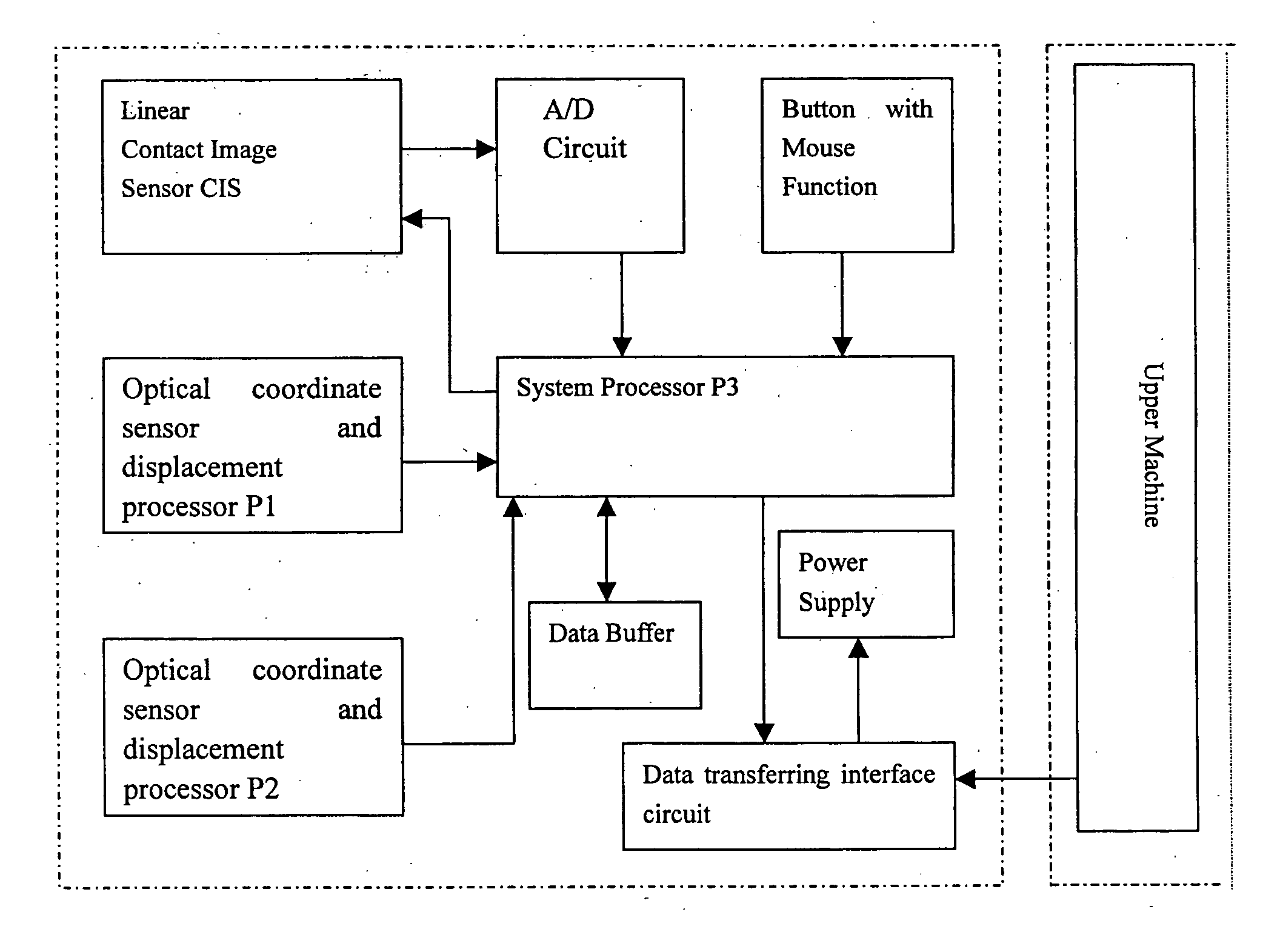
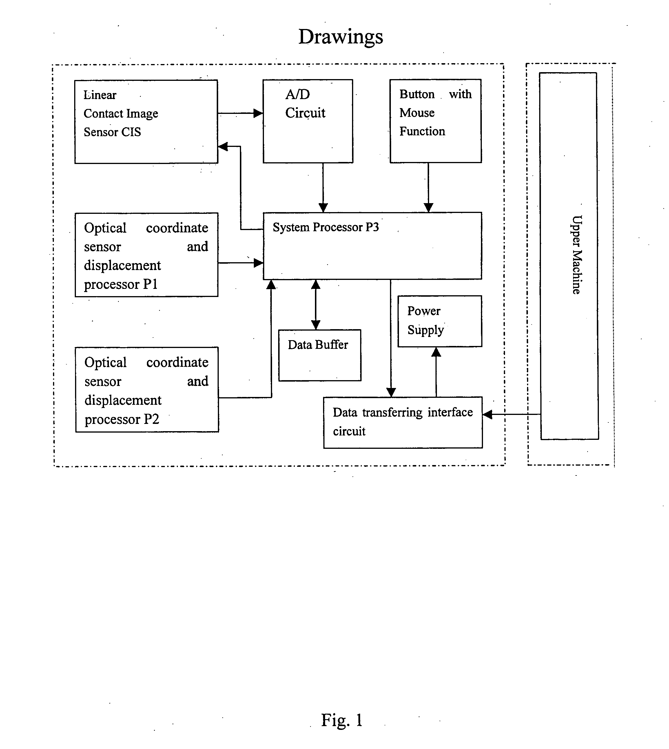
[0025]FIG. 1 illustrates a circuit structure of the present invention, wherein includes a system processor P3, optical coordinate sensor and displacement processor P2, linear contact image sensor (CIS), A / D circuit, button with mouse function, power supply circuit, data buffer and data transferring interface circuit; and is connected to an upper machine via the data transferring interface circuit. The first optical coordinate sensor and the first displacement processor P1 estimate out the first coordinate increment (8001), and the second optical coordinate sensor and the second displacement processor P2 estimate out the second coordinate increment (8002). The coordinate increment (8001) and the coordinate increment (8002) are then transferred to the system processor P3; the system processor P3 controls the linear contact image sensor (CIS) through ON-OFF signal and timing signal from mouse-functional buttons to acquire analog image scanning data and then transfer them to the A / D cir...


PUM


Abstract

The present invention relates to a scanning device with a positioning senor and a processing method to obtain images, comprising a casing, linear contact image sensor (CIS), further comprising a system processor P3 for controlling the work of said CIS by timing signal, the optical coordinate sensors and the displacement processor P1 and P2 for estimating the coordinate increment (8001) and the coordinate increment (8002) of the real-time displacement, an A / D circuit and data buffer; said system processor P3 packets original scanning data with positioning information (8004), and then transfers to the upper machine. An image processing module in the upper machine de-packets said original scanning date (8004); Converts out the coordinate of the terminal pixel of said linear contact image sensor (CIS), and configures the image line in the object image configuring area; and calculates and rectifies the relative offset of the positioning coordinate of the two scanning bands making using of the statistical characteristic of part of pixel data in the overlapped area of the two scanning bands.

Description

FIELD OF THE INVENTION [0001] The present invention relates to an optical scanning technology, particularly to a scanning device with a positioning senor and a corresponding processing method to obtain images. BACKGROUND OF THE INVENTION [0002] The traditional scanners are plate scanners. The images to be scanned are placed at the scanning window of the scanners, behind which the image sensor moves to acquire data of the scanned images. Such structure has large volume and is of heavy weight. Afterwards, the paper-feeding scanners came into existence, the media of the images to be scanned are driven to move across the scanning window of strip shape, and then the image sensor acquires data of the image to be scanned. Although such structure has decreased volume and weight, but it is inconvenient to scan all images of a whole book. As a result, the handhold scanning brush and scanning pen of smaller volume came into being. Users move such scanners by hand across the media to be scanned...

Claims


Application Information

Patent Timeline
Patent Type & Authority Applications(United States)
IPC IPC(8): G06K9/00H04N1/028H04N1/031H04N1/04H04N1/047H04N1/107
CPCH04N1/0318H04N1/047H04N1/107H04N2201/04787H04N2201/0471H04N2201/04713H04N2201/04743H04N2201/0468
Inventor ZHANG, WEIZHANG, FUCHANG, ZHIGUOLV, YINGFENGGU, CHENGWUDING, XIAOYUN
Owner SHENZHEN SYSCAN TECHC CO LTD
Why Eureka
Try Eureka