[0053] Another
advantage of the present invention associated with the contiguous and complete contact between the conformal EMI shield and the coated printed circuit board surfaces is that it does not create a
thermal insulation of “dead air” space around the shielded components. In fact, because the conformal EMI shield is a thin, continuous layer that is physically attached to the surfaces of the printed circuit board, it promotes the distribution of heat away from the coated printed circuit board regions rather than serving as a thermal insulator. Specifically, the conformal EMI shield conducts heat away from the component to the surface of the
conductive coating where it is either dissipated through
convection to the surrounding environment or conducted to a
heat sink.
[0054] As noted, conventional product enclosures comprises cooling holes and fans to circulate air around the printed circuit board and metallic EMI boxes. An associated benefit of the present invention is that the size restrictions on the cooling holes and fan grills on the product enclosures is eliminated since there is no longer a need to remove heat emanating from a high temperature metallic EMI box on the printed circuit board.
[0055] A further
advantage of the present invention is that it eliminates the need for all other types of EMI shielding components. In particular,
elimination of conventional metallic EMI boxes reduces the cost and the weight of the sheet
metal. This, in turn, eliminates the constraints on
package design imposed by such conventional approaches. Furthermore, the associated shielding components such as gaskets and spring contacts are eliminated, reducing the associated cost and complexity. 2. Conformal EMI Shield Materials
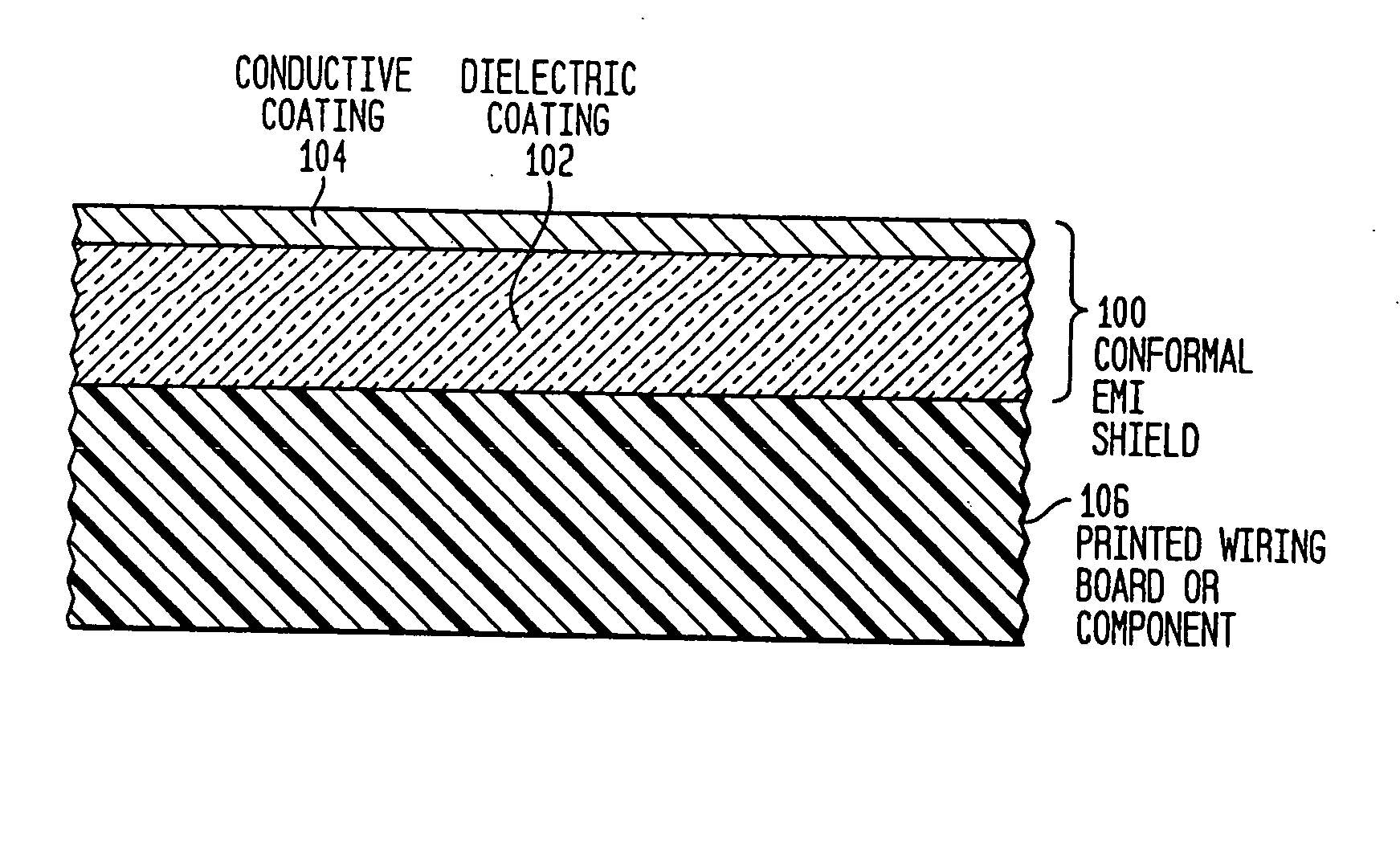
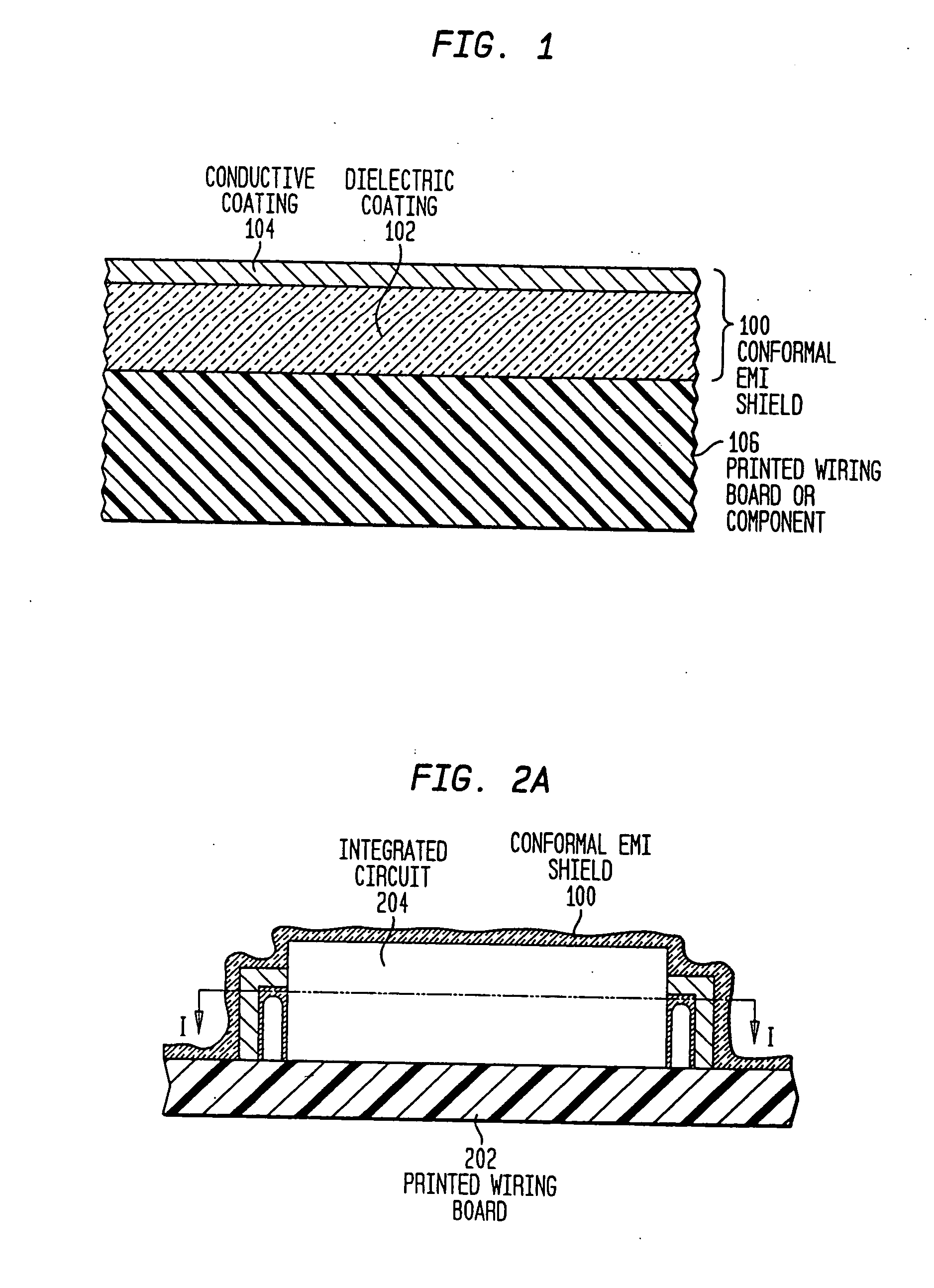
[0057] As noted, the conformal EMI shield includes a conductive coating and a dielectric coating permanently bonded to each other. The materials that can be used in the conductive and dielectric coatings are described below with reference to FIGS. 1-3. FIG. 1 is a cross-sectional view of one embodiment of the conformal EMI shield of the present invention. FIG. 2A is a cross-sectional view of an
integrated circuit component mounted on a printed wiring board forming a portion of a printed circuit board. The
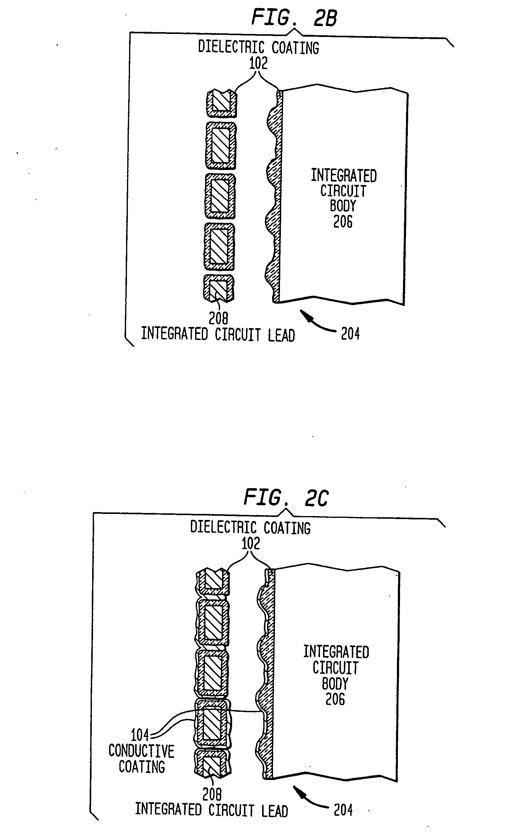
integrated circuit component and printed wiring board have been coated with one embodiment of the conformal EMI shield of the present invention. FIG. 2B is a top view of the
integrated circuit component illustrated in FIG. 2A taken along section line I-I illustrating the application of the shield's dielectric coating in accordance with one embodiment of the present invention. FIG. 2C is a top view of the integrated circuit component taken along the same section line illustrating the application of the conformal EMI shield's conductive coating in accordance with one embodiment of the present invention.
[0058] Referring now to FIG. 1, this embodiment of EMI shield 100 includes a dielectric coating 102 and a conductive coating 104. The exposed surfaces of selected printed circuit board regions 106 are coated with conformal EMI shield 100. Such surfaces can be, for example, the top, side and, if exposed, bottom surface of a component, the surface of any leads, wires, etc, that are connected to the component, as well as any other exposed surface of any other portions, elements, sections or features (hereinafter “features”) of the components and printed wiring board located in the coated printed circuit board region. It should be appreciated that the selection of the combination of material properties for dielectric coating 102 and conductive coating 104 is important to achieving a conformal EMI shield that can be applied directly to printed circuit board surfaces without damaging components and connections, that does not
expose the coated regions to risk of electrical shorts, and that completely envelops or encases the coated regions to provide a desired shielding effectiveness. As will be described in detail below, conformal EMI shield 100 not only achieves such operational objectives, but does so, as noted, by directly coating; that is, physically adhering to, the surface of coated printed circuit board regions. This enables conformal EMI shield 100 to completely and conformingly coat the surfaces of the shielded printed circuit board regions.
[0060]
Dielectric coating 102 is comprised of a material that is electrically nonconductive and, preferably, thermally conductive. Importantly, the material properties of dielectric coating 102, described in detail below, enable dielectric coating 102 to completely coat and securely attach to component and board surfaces to which it is applied. Generally, the material properties of dielectric coating 102 include primarily a combination of
viscosity and adhesion sufficient to enable dielectric coating 102 to be applied via atomization spray techniques and, once applied, to adhere to the surface in the immediate vicinity of where it was applied. In other words, adhesiveness of dielectric coating 102 is sufficient to prevent dielectric coating 102 from separating from the surface to which it is applied prior to curing, a phenomenon commonly referred to as
dewetting. Such a condition will otherwise result in a void in dielectric coating 102, providing the potential of an electrical short in the exposed portion of printed wiring board or component 106.
Dielectric coating 102 can comprise multiple, successively applied
layers of dielectric material. As such, dielectric material 102 preferably also includes the properties necessary to enable it to adhere to or bond with previously applied dielectric
layers.

