
Apparatus and method for low pressure wirebond

a low-pressure wire bonding and apparatus technology, applied in the direction of soldering apparatus, manufacturing tools,auxillary welding devices, etc., can solve the problems of general dielectric material propensity, failure to pull out or delamination of pads and associated materials underneath pads, distortion or cracks in electrodes or substrates, etc., to reduce the propensity of dielectric materials

Inactive Publication Date: 2005-05-12
GLOBALFOUNDRIES INC
View PDF21 Cites 27 Cited by
  • Summary
  • Abstract
  • Description
  • Claims
  • Application Information

AI Technical Summary

Benefits of technology

[0013] It is yet another object of the present invention to provide an apparatus and method ...

Problems solved by technology

One type of failure is produced by the ball at the end of the bonding wire, which, being mechanically hard brings about structural deformation and destruction of the substrate upon compression.
Another type of failure is pulling out or delamination of pads and associated material underneath pads as the wire is pulled off the spool after the first end is bonded to the pad.
This could be the result of tensile pulling of the wire, or exacerbated by brittle fracture damage under the pad during the compression phase of bonding.
This method, however, has problems in that distortions or cracks are generally produced in the electrode or substrate.
As is presently known in the art, low-k dielectric materials are easily damaged during wire bond operations.
Insertion of a wire bond may cause excessive forces that could otherwise distort, stress, or crack the pad and underlying substrate material.
Furthermore, the strength of the bond is jeopardized if micro cracks are introduced during the bonding process.
However, since copper has a tendency to corrode when exposed to environmental conditions, when used in interconnect metallurgy to diffuse into surrounding dielectric materials, such as silicon dioxide, capping of the copper is essential.
However, some barrier layers are subject to delaminating under conditions of mechanical loading.
Moreover, a wire bonded to a barrier layer that is structurally deficient provides a weak contact point that ultimately jeopardizes the semiconductor's integrity and reliability.
A similar approach is taken in Costrini et al., for wirebond pad terminals, in U.S. Pat. No. 6,187,680, entitled “METHOD / STRUCTURE FOR CREATING ALUMINUM WIREBOND PAD ON COPPER BEOL.” However, the Al(Cu) and barrier layers do not allow for a decrease in the necessary bonding pressure, temperature, or ultrasonic energy required to bond a wire.
Further, the method of forming the multilayered barrier plus Al(Cu) pad involves expensive lithographic and reactive ion etching (RIE) steps, which are undesirable.
The quaternary alloy layer, however, is not used for facilitating wire bonding or reducing the bonding pressures, temperatures, or ultrasonic energy.
The resulting surface is already in an alloy form, and does not facilitate in wirebonding by reducing pressure or energy to form the bond.

Method used


Image

  • Apparatus and method for low pressure wirebond
  • Apparatus and method for low pressure wirebond
  • Apparatus and method for low pressure wirebond

Examples


Embodiment Construction

)

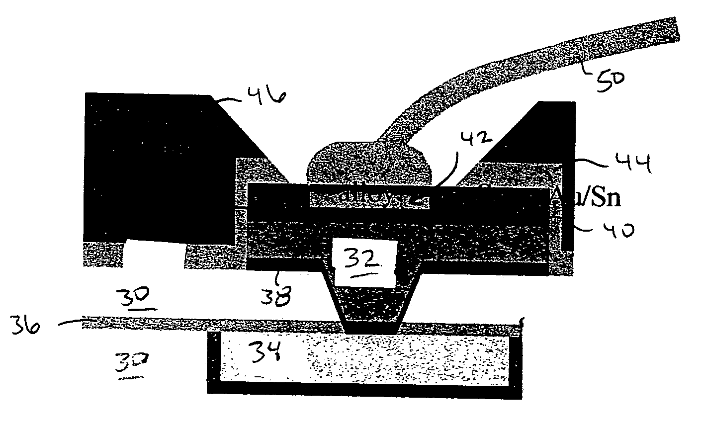
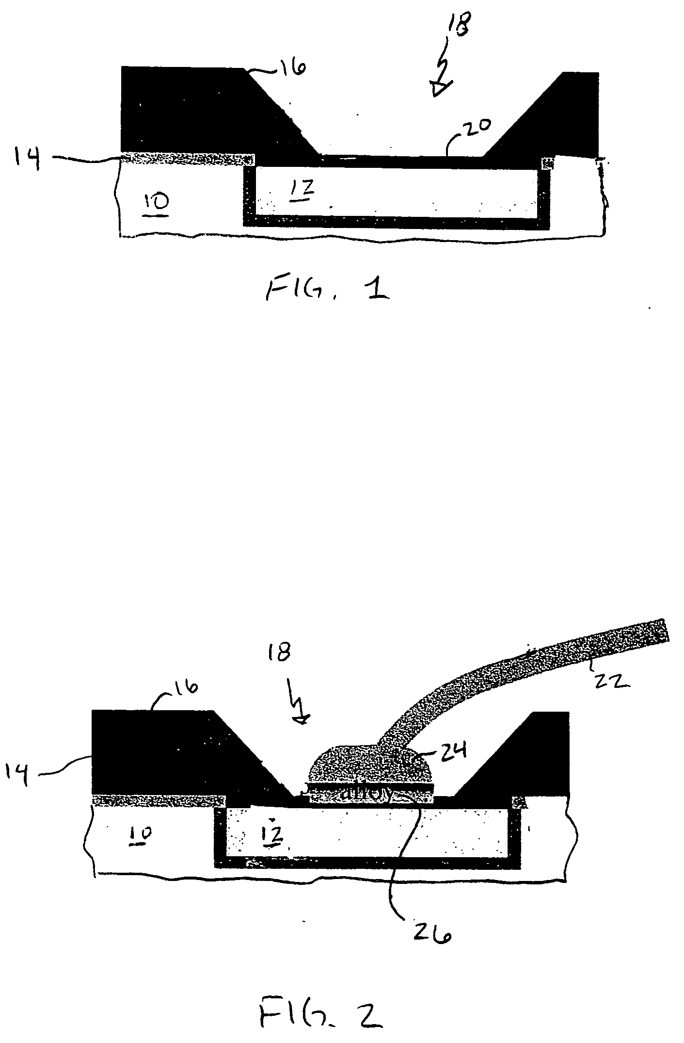
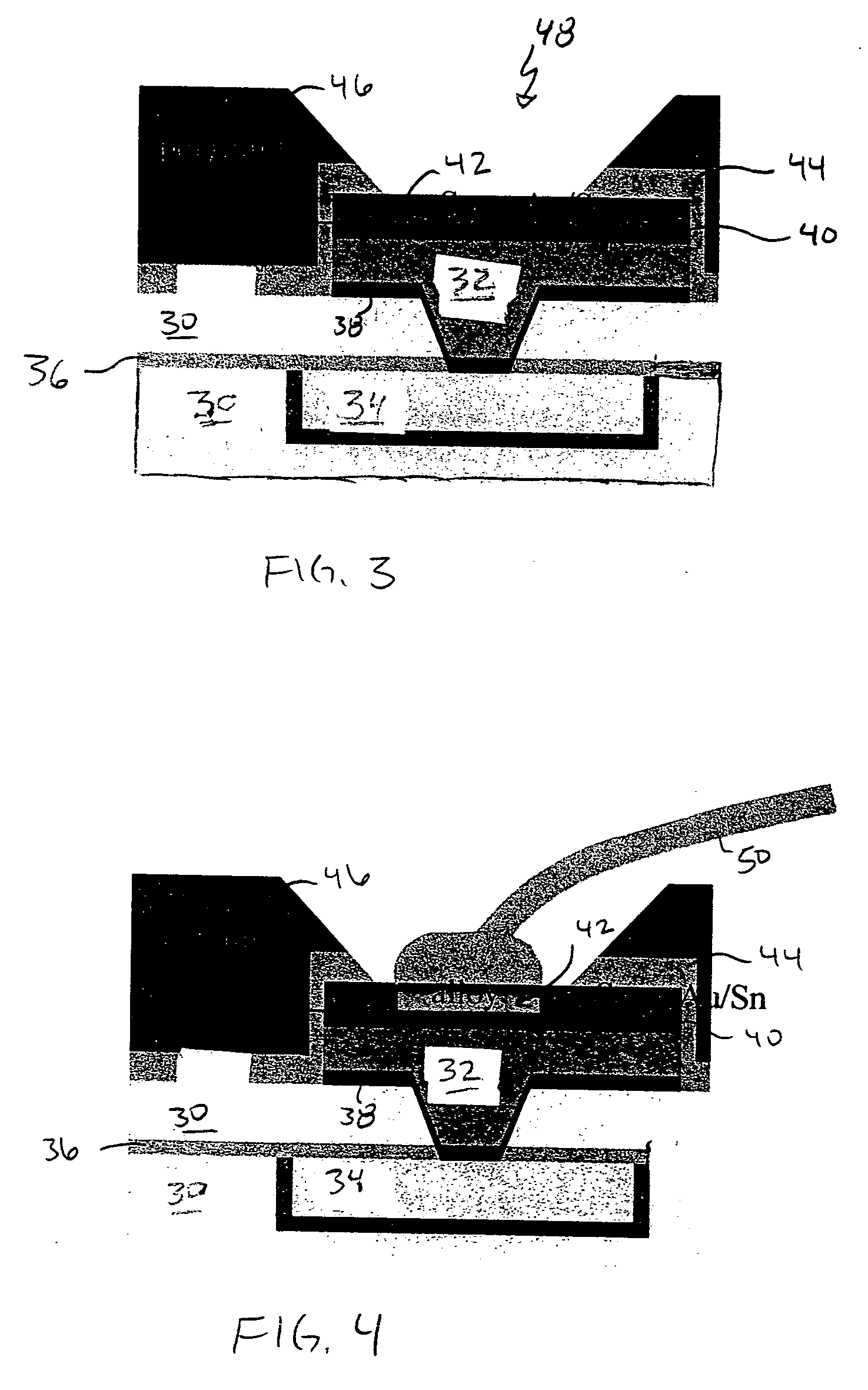
[0026] In describing the preferred embodiment of the present invention, reference will be made herein to FIGS. 1-4 of the drawings in which like numerals refer to like features of the invention.

[0027] Dielectrics have poor mechanical strength and are subject to cracking. Wirebonding to a semiconductor can induce cracks / damage in the dielectric when stresses are applied. The cracking can result in reliability failures during use. The present invention details an apparatus and method for low-pressure wirebonding, which reduces the propensity of dielectric material to mechanical failure due to wirebond stress.

[0028] An approach is presented to increase the reactivity between the bond wire and the bond pad, thereby allowing for reduced pressure and ultrasonic and thermal energy during wirebonding. This approach is to use a metal alloy on top of the bond pad that reacts at low temperatures with the bond wire.

[0029] A low temperature alloying metal on the surface of the pad can allow ...


PUM

PropertyMeasurementUnit
Temperatureaaaaaaaaaa
Pressureaaaaaaaaaa
Concentrationaaaaaaaaaa

Abstract

A structure and method for low-pressure wirebonding, reducing the propensity of dielectric material to mechanical failure due to wirebond stress. A low temperature alloy on the surface of a bond pad allows alloy bond formation to occur between the wire and the bond pad at reduced bond pressures and reduced thermal and ultrasonic energies. Preferred alloys include Au—Sn and Au—In. The Au—Sn alloy may be formed over the Cu bond pad, incorporated in an aluminum bond pad stack, or deposited on a bond pad having Ni—Au capping of Cu or Al bond pads.

Description

BACKGROUND OF THE INVENTION [0001] 1. Field of the Invention [0002] The present invention relates to wire bonding for semiconductor substrates, and more particularly to a wire bonding method and apparatus that reduces the pressure, temperature, and energy required for bonding. The present invention is particularly applicable for bonding to low-k dielectric material that is susceptible to cracking under applied pressure and temperature. [0003] 2. Description of Related Art [0004] Semiconductor devices comprising semiconductor chips and lead frames are well known. A semiconductor integrated circuit (IC) chip having one or more semiconductor-based circuits wired by metal interconnects, with terminal inputs and outputs to external circuitry, is generally mounted on a mounting area of a lead frame, and each input / output (IO) terminal is connected with a lead of the lead frame by a thin bonding wire typically of gold or aluminum. In an integrated circuit chip, regions are usually connecte...

Claims


Application Information

Patent Timeline
IPC IPC(8): B23K20/00H01L23/485
CPCB23K20/007H01L24/03H01L24/05H01L24/45H01L24/48H01L24/85H01L2224/02166H01L2224/04042H01L2224/05083H01L2224/05124H01L2224/05147H01L2224/05609H01L2224/05611H01L2224/05644H01L2224/45144H01L2224/48091H01L2224/48463H01L2224/85205H01L2224/85359H01L2224/85801H01L2924/01006H01L2924/01013H01L2924/01014H01L2924/01015H01L2924/01022H01L2924/01027H01L2924/01028H01L2924/01029H01L2924/0105H01L2924/01073H01L2924/01074H01L2924/01078H01L2924/01079H01L2924/01082H01L2924/01322H01L2924/014H01L2924/04941H01L2924/04953H01L2924/05042H01L2924/14H01L2924/01019H01L2924/01033H01L2224/48611H01L2224/48609H01L2224/48644H01L2924/00014H01L2924/01049H01L2924/00H01L2224/45124H01L2224/48709H01L2224/48711H01L2224/48744H01L2224/85203H01L2924/00015
Inventor EDELSTEIN, DANIEL C.FITZSIMMONS, JOHN A.GAMBINO, JEFFREY P.STAMPER, ANTHONY K.
Owner GLOBALFOUNDRIES INC
Learn More