
Light weight helicopter

a helicopter and light-weight technology, applied in the field of light-weight helicopters, can solve the problems of increasing aerosports, difficult to learn to operate and fly safely, and expensive training in a 2-seater, and achieve the effect of simple flying and simplified construction

Inactive Publication Date: 2005-05-12
COUNCIL OF SCI & IND RES
View PDF3 Cites 17 Cited by
  • Summary
  • Abstract
  • Description
  • Claims
  • Application Information

AI Technical Summary

Benefits of technology

[0005] The use of two counter-rotating rotors is employed in some helicopters, such as for example, the Kamov helicopter of Russian origin and reported in Janes “Aircraft of the World”. The use of counter-rotating concentric rotors has the advantage of having a zero net angular momentum thus avoiding the requirement of a tail rotor for torque balancing required in the single main—rotor arrangement as in the conventional helicopters. There is a saving in power normally consumed by the tail rotor of a conventional helicopter. However, due to the lower rotor being placed in the wake of the upper rotor, there is an interference effect which results in an increase in the power required for a given thrust, thus nullifying to some extent, the saving in power of the tail rotor. Another feature of the Kamov concentric contrarotating rotors in the use of differential pitch control of the two rotors for achieving control in the yaw direction. This machine therefore needs a collective pitch, a cyclic pitch and differential pitch arrangements for its control. With all these features, the mechanical complexity is very high, leading to an expensive and complex machine.
[0007] The main object of the present invention is to provide lightweight helicopter of simplified construction, which is simple to fly and overcomes the drawbacks noted above. This machine is appropriately termed as “helitrike”. DETAILED DESCRIPTION OF THE INVENTION
[0008] Accordingly, the present invention provides a lightweight helicopter of simplified construction, which is simple to fly and is appropriately termed as “helitrike”.

Problems solved by technology

While a number of affordable aircraft such as ‘microlights, powered hang gliders have brought the possibilities of powered flight within the reach of general public, leading to an upsurge in aerosports, the same is not true of the helicopter.
The helicopter remains an expensive machine to acquire and difficult to learn to operate and to fly safely.
15 lakhs) in kit form and would require expensive training in a 2-seater helicopter, which may require 100 hrs and cost Rs.6-8 lakhs for the training.
This difference arises mainly due to the increased complexity of the conventional helicopter, which results in an expensive machine, which is difficult to learn to fly.
This invention has several drawbacks: since the pilot is freely suspended in a supine position under the downwash of the rotors, it is likely that it will lead to large swaying and buffetting of the pilot, making it difficult to control the aircraft.
The supine (face downward) position is also considered to be extremely dangerous from a crash-worthiness point of view.
Another drawback of the invention is that in hover and low forward speeds, the absence of a positive control in the yaw direction could lead to undesirable spinning of the pilot about a vertical axis.
It appears very difficult to introduce any further controls to overcome this problem, since both the hands of the pilot are fully occupied in manipulating the control bar, the rotor blade pitch control and the engine throttle and the pilots' feet are not available to carry out any control function because of the supine, freely hanging position.
However, due to the lower rotor being placed in the wake of the upper rotor, there is an interference effect which results in an increase in the power required for a given thrust, thus nullifying to some extent, the saving in power of the tail rotor.
With all these features, the mechanical complexity is very high, leading to an expensive and complex machine.
Thus the HT-1 (1) could achieve the ultralight category but it may be somewhat under-powered and the HT-1 (2) could have sufficient power but would not meet the ultralight category weight limit.

Method used


Image

  • Light weight helicopter
  • Light weight helicopter
  • Light weight helicopter

Examples


Embodiment Construction

[0008] Accordingly, the present invention provides a lightweight helicopter of simplified construction, which is simple to fly and is appropriately termed as “helitrike”.

[0009] The detailed description of the helitrike is described hereunder with the help of the following drawings.

BRIEF DESCRIPTION OF THE ACCOMPANY DRAWINGS

[0010] The details of the helicopter of the present invention are shown in FIGS. 1-4 of the drawings accompanying this specification.

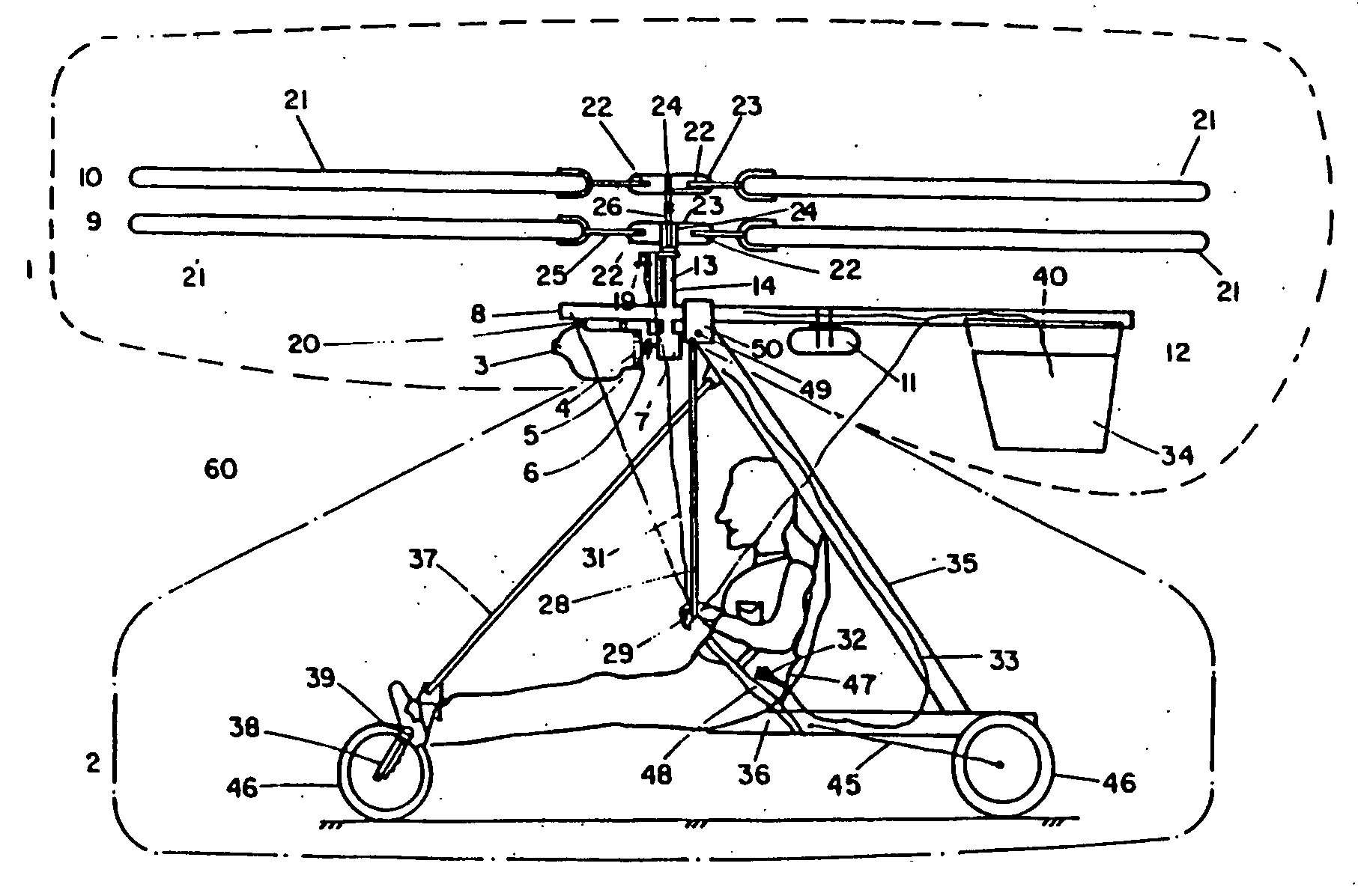
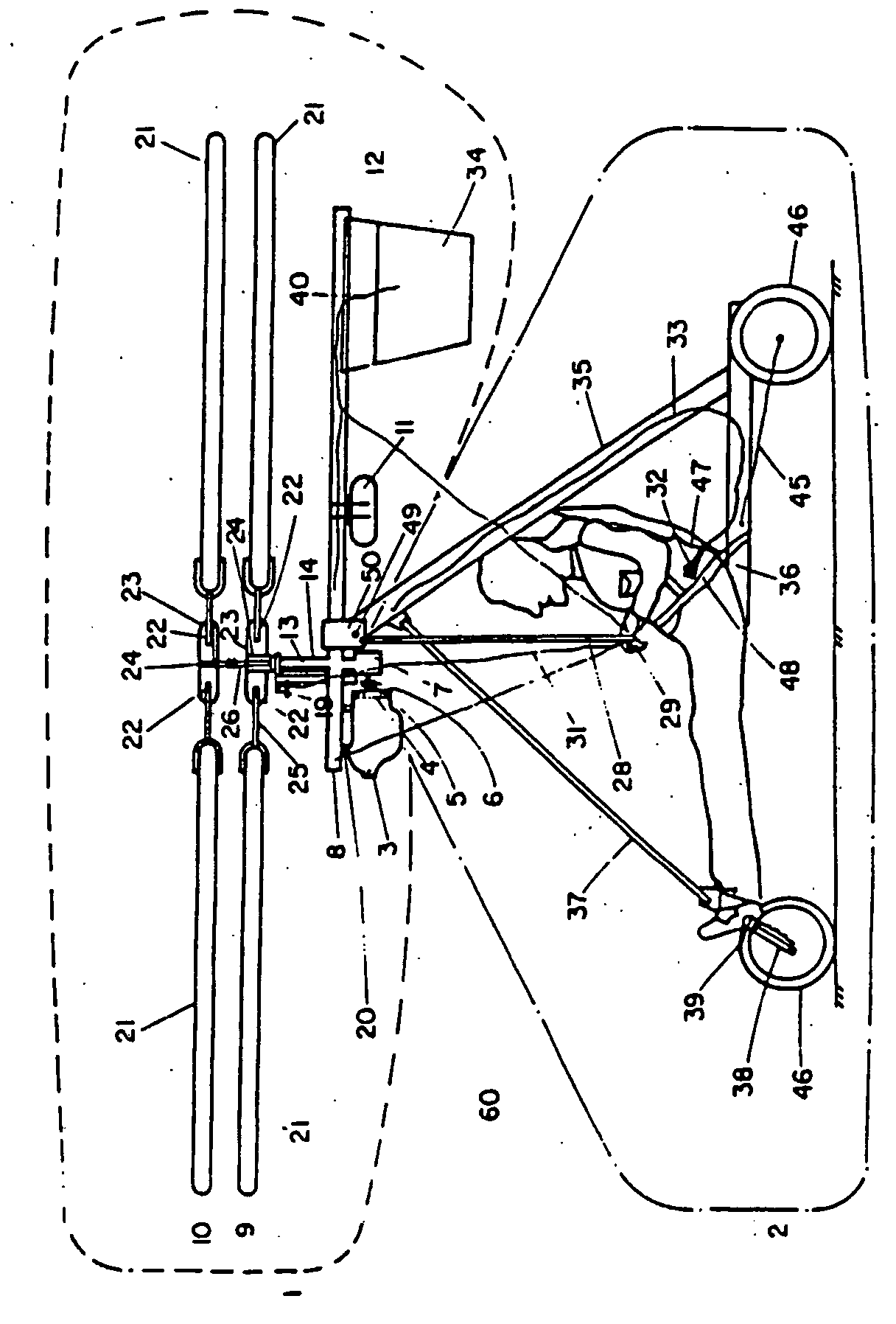
[0011]FIG. 1 shows the side view of helitrike.

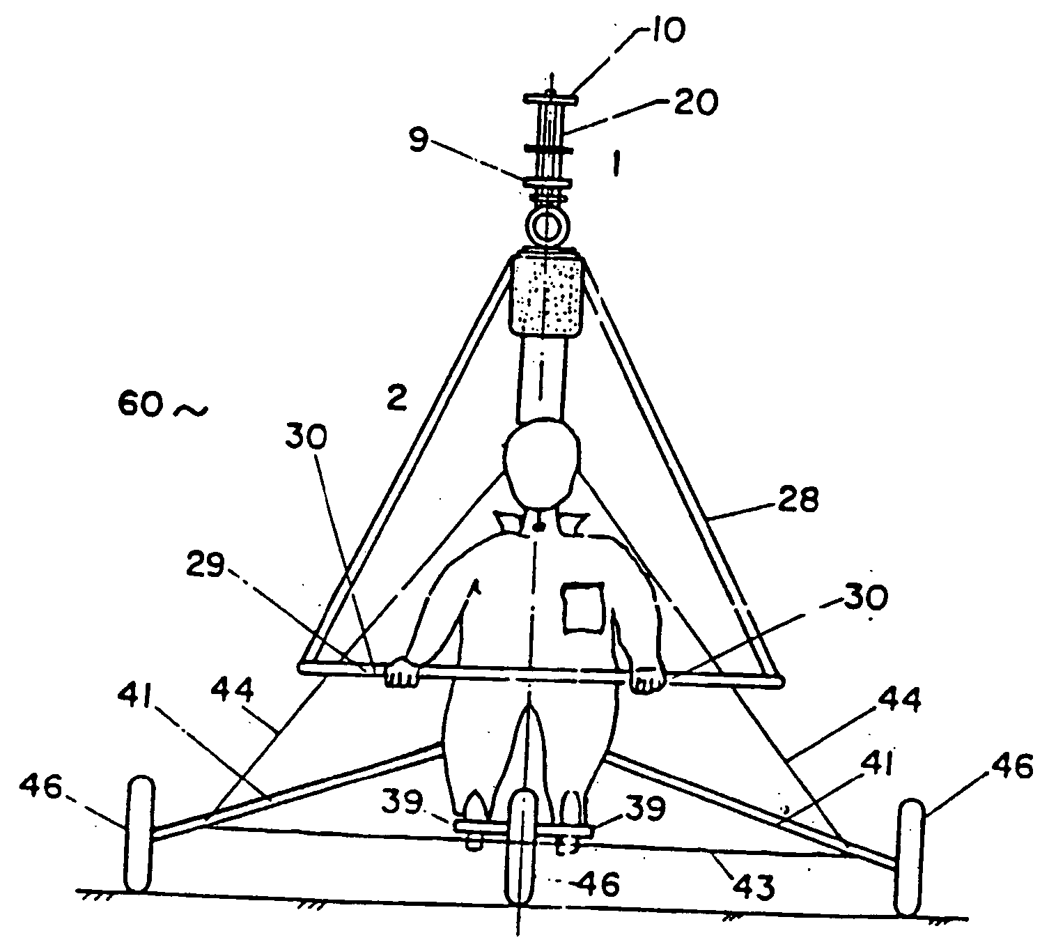
[0012]FIG. 2 shows the front view of helitrike.

[0013]FIG. 3 shows a cross-sectional view of the secondary gearbox.

[0014]FIG. 4 shows a view of the suspension arrangement.

[0015]FIG. 5 is a plot of power loading and disk loading of some typical light helicopters.

[0016] Accordingly, the present invention provides a light weight helicopter which comprises: a rotary wing unit (1) consisting of an engine (3) with a primary gearbox (4) connected through flexible coupling (5) and sprag clu...


PUM


Abstract

The present invention relates to a lightweight helicopter, comprising of a rotary wing (1) unit and a frame assembly (2), the rotary wing consists of an engine (3) with a primary gear box (7), mounted below a keel post (8) and the keel post attached to a triangular control frame (28), the base of which forms the control bar (29), and is also provided with a tail plane (12) having one or more vertical articulable flaps (34). A secondary gearbox is provided with means capable of transmitting the rotary movement of the said engine to two horizontal rotors (9, 10) capable of pitch change. The rotary wing unit is suspended by means to a frame assembly having means (47) for pilot seating, landing gear (46) and provided with means for control of the engine, rotors, tailplane and landing gear.

Description

TECHNICAL FIELD [0001] The present invention relates to a lightweight helicopter. BACKGROUND AND PRIOR ART [0002] The present invention provides for a lightweight helicopter which is simple to operate and affordable for individuals or groups for purposes of aero-sports and hobby flying. While a number of affordable aircraft such as ‘microlights, powered hang gliders have brought the possibilities of powered flight within the reach of general public, leading to an upsurge in aerosports, the same is not true of the helicopter. The helicopter remains an expensive machine to acquire and difficult to learn to operate and to fly safely. For example a single seater, powered hand glider manufactured indigenously is available for about Rs.2.0 lakhs and requires about 10-15 hours instruction before an average person can fly solo. On the other hand, the recently introduced single seater “Ultralight Helicopter”, the Ultrasport 254 in the USA costs around $35,000 (Rs. 15 lakhs) in kit form and w...

Claims


Application Information

Patent Timeline
IPC IPC(8): B64C27/10B64C31/028B64C39/02
CPCB64C27/10B64C39/026B64C31/028
Inventor PAI, BHASKAR RAMCHANDRA
Owner COUNCIL OF SCI & IND RES
Learn More