Pressure-enhanced, adaptive inflator device

a technology of inflator and pressure, which is applied in the direction of pedestrian/occupant safety arrangement, vehicle components, weapons, etc., can solve the problems of increasing one or more of the size, cost and weight of the inflator device, difficult to provide an adaptive inflator, and simple enlargement of such vents that may not be practical or feasible for an installation to achieve or provide desired adaptive performance, etc., to achieve high burn rate pressure dependency, controllable net operating pressure within the inflator devi

Inactive Publication Date: 2005-05-12
AUTOLIV ASP INC
View PDF21 Cites 13 Cited by
  • Summary
  • Abstract
  • Description
  • Claims
  • Application Information

AI Technical Summary

Benefits of technology

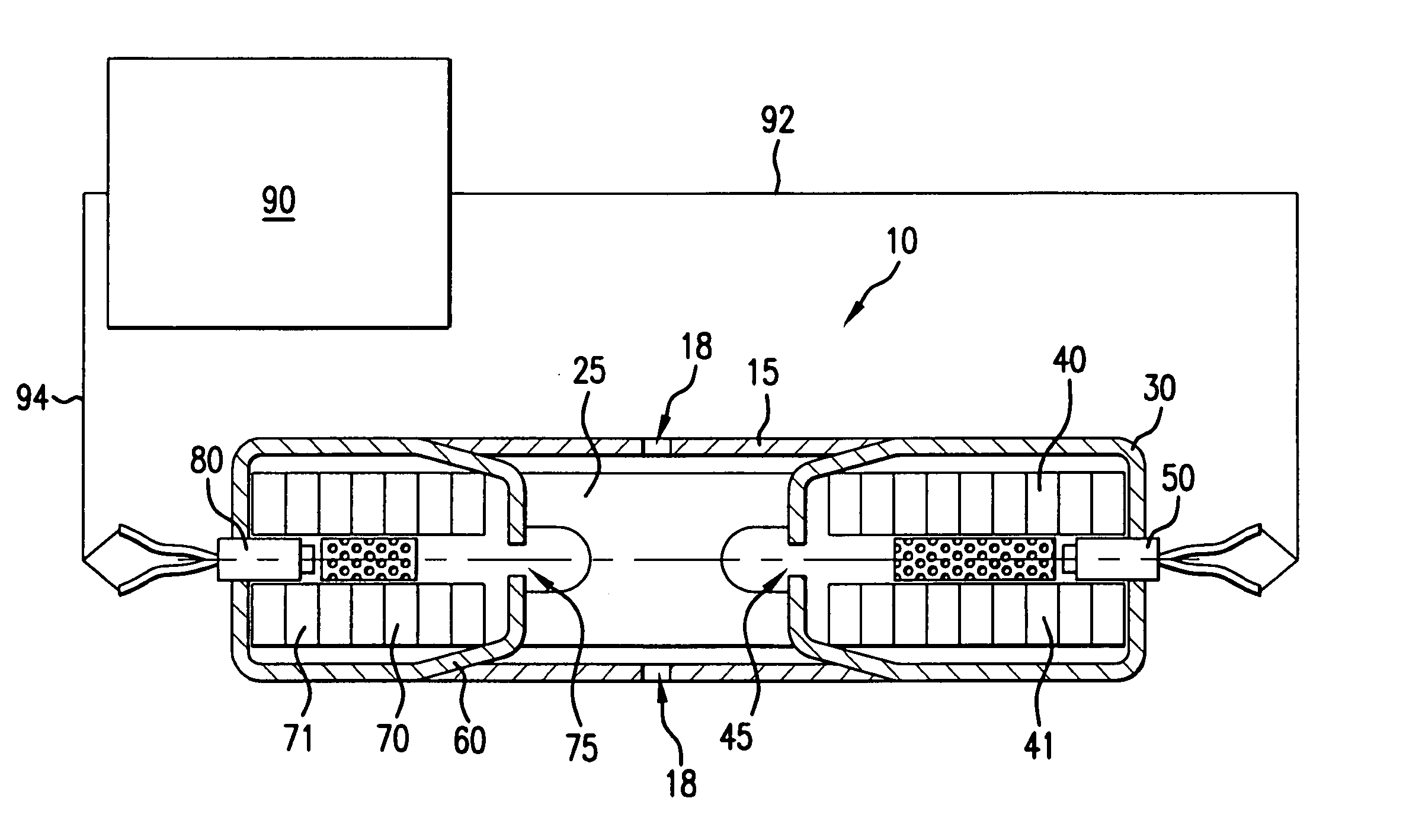
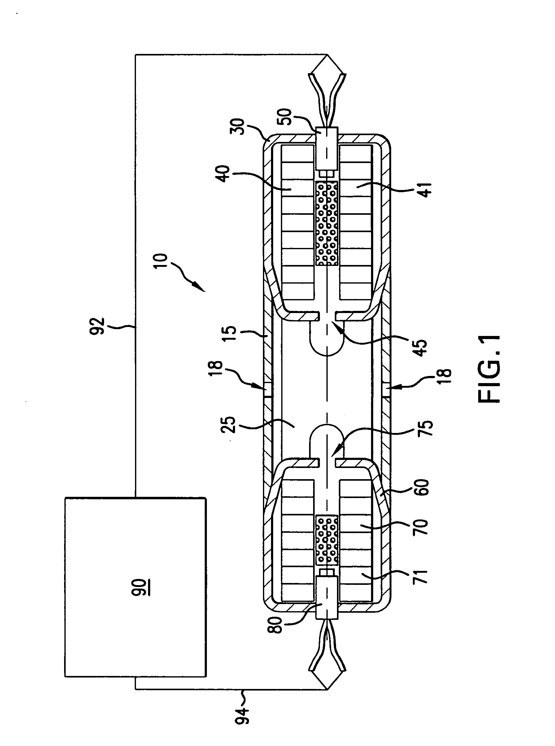
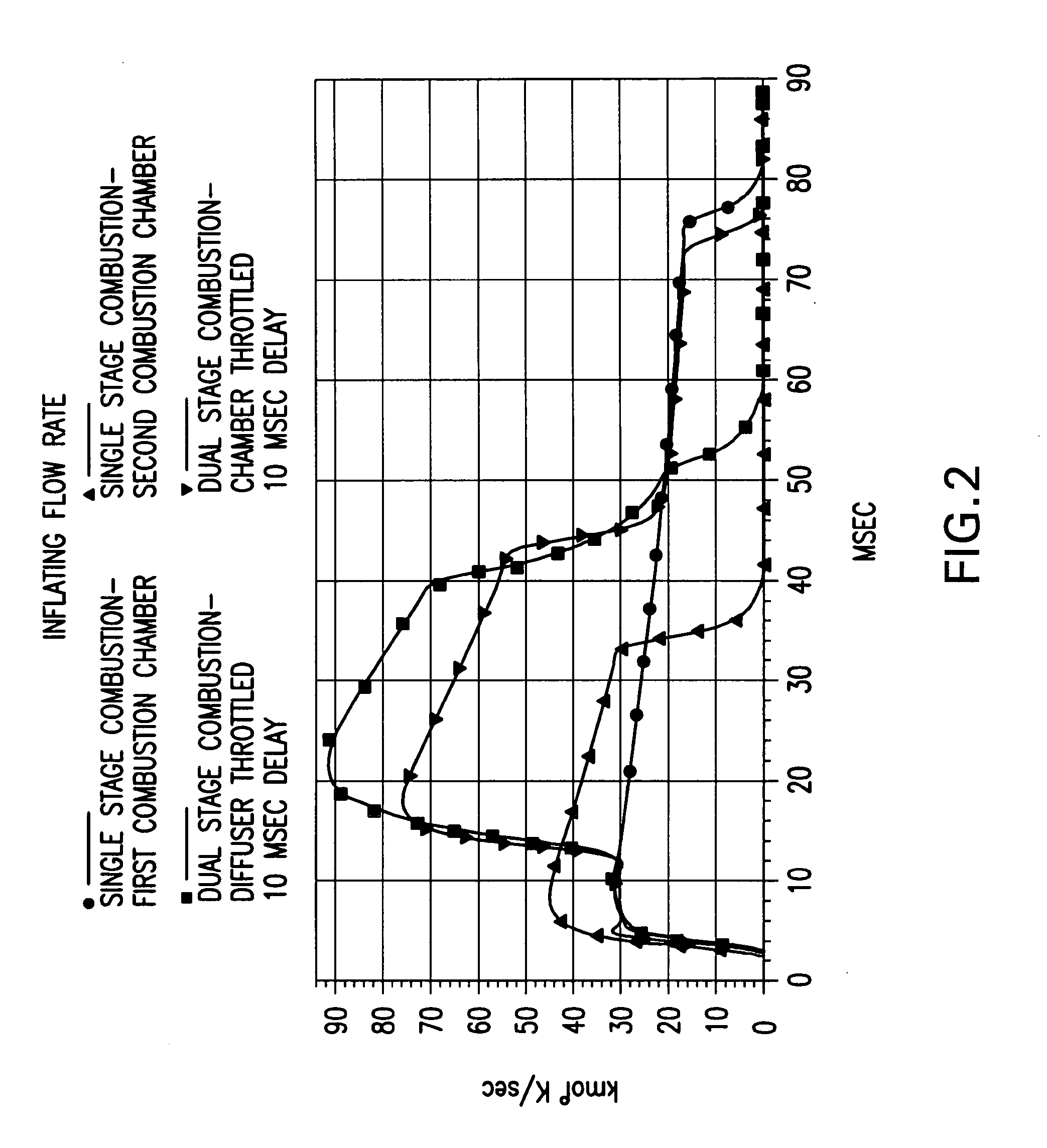
[0026] In accordance with a preferred embodiment of the invention, with operation of only one of the first or the second combustion chambers, the inflation fluid flow is too low or insufficient for the orifice area of the diffuser to serve as a controlling orifice or otherwise choke the inflation gas flow therethrough. However, with both the first and the second combustion chambers operating, the combined inflation fluid flow is sufficiently great as to overwhelm the diffuser exit area (e.g., the diffuser orifices). As a result, the flow choke point or throttling orifice area is effectively moved or relocated from the exit areas or orifices of each of the combustion chambers, respectively, to the diffuser exit area (e.g., the diffuser orifices) and such that the net operating pressure within the inflator device is controllably increased. As will be appreciated by those skilled in the art and guided by the teachings herein provided, varying effects are attainable by employing a gas generant having a high burn rate pressure dependency in either or both chambers of an inflator device in accordance with the invention. For example, in accordance with certain preferred embodiments of the invention and when using a gas generant having a high burn rate pressure dependency, the benefits resulting from such operation may desirably include a longer burn time or duration for a single chamber combustion operation and a shorter burn time or duration for a dual chamber combustion operation.

Problems solved by technology

The use of sodium azide and certain other azide-based gas generant materials may, however, involve or raise potential concerns such as involving handling, supply and disposal of such materials.
While such adaptive systems are desirable, they typically require the inclusion of additional components as a part of the associated inflator device and such as may undesirably increase one or more of the size, cost and weight of the inflator device.
Thus, it has been difficult to provide an adaptive inflator which will satisfactorily meet the size, cost and weight limitations associated with modern vehicle design.
Moreover, while passive restraint cushions may incorporate vents such as to permit the controlled deflation or venting of the cushion after inflation, the simple enlargement of such vents may not be practical or feasible for an installation to achieve or provide desired adaptive performance.
For example, such an increase in cushion ventilation may undesirably decrease the effectiveness of the cushion and inflator device during a single stage combustion where only the single stage combustion is actuated, such as may be desired in response to a low speed crash incident.

Method used


Image

  • Pressure-enhanced, adaptive inflator device
  • Pressure-enhanced, adaptive inflator device
  • Pressure-enhanced, adaptive inflator device

Examples


examples

[0063] In these tests, an inflator device in accordance with one preferred embodiment of the invention, as shown in FIG. 1, was used. The test inflator included: [0064] 1) as the supply of the first gas-generating pyrotechnic material a propellant in accordance with the above-identified Taylor et al., U.S. Pat. No. 6,103,030, issued 15 Aug. 2000, and which pyrotechnic material had a burn rate (rb) of 0.45 inch per second at a pressure of 1000 and a pressure exponent (n) of 0.65; and [0065] 2) as the supply of the second gas-generating pyrotechnic material a propellant in accordance with Mendenhall et al., U.S. 2003 / 0106624, published 12 Jun. 2003, and which pyrotechnic material (included: approximately 54 weight percent basic copper nitrate, approximately 25 weight percent guanidine nitrate, approximately 20 weight percent copper complex of diammonium bitetrazole, and approximately 1-2 weight percent aluminum oxide) had a burn rate (rb) of 1.06 inch per second at a pressure of 1000 ...


PUM


Abstract

An inflator device that includes a diffuser chamber with a first combustion chamber and a second combustion chamber each connected to the diffuser chamber. A supply of a first gas-generating pyrotechnic material having a burn rate that is pressure dependent is contained within the first combustion chamber. The first combustion chamber forms or includes an orifice providing independent fluidic communication between the first combustion chamber and the diffuser chamber. This orifice throttles a single stage combustion wherein the supply of the first gas-generating pyrotechnic material is selectively reactable to produce a first combustion chamber single stage combustion product gas. A supply of a second gas-generating pyrotechnic material is contained within the second combustion chamber. The second combustion chamber forms or includes an orifice that provides independent fluidic communication between the second combustion chamber and the diffuser chamber. This orifice throttles a single stage combustion wherein the supply of the second gas-generating pyrotechnic material is selectively reactable to produce a second combustion chamber single stage combustion product gas. The diffuser chamber forms or includes at least one exit orifice. This diffuser exit orifice throttles a dual stage combustion wherein the supply of the first gas-generating pyrotechnic material is reactable to produce a first combustion chamber dual stage combustion product gas and the supply of the second gas-generating pyrotechnic material is reactable to produce a second combustion chamber dual stage combustion product gas.

Description

BACKGROUND OF THE INVENTION [0001] This invention relates generally to inflator devices such as for use in inflating inflatable restraint airbag cushions to provide impact protection to occupants of motor vehicles. More particularly, the invention relates to inflators which rely primarily on reaction of a combustible material for the production of an inflation gas and such as may provide an inflation gas output which is adaptive to factors such as one or more crash and occupant conditions. [0002] It is well known to protect a vehicle occupant using a cushion or bag, e.g., an “airbag,” that is inflated or expanded with gas when the vehicle encounters sudden deceleration, such as in a collision. In such systems, the airbag cushion is normally housed in an uninflated and folded condition to minimize space requirements. Upon actuation of the system, the cushion begins being inflated in a matter of no more than a few milliseconds with gas produced or supplied by a device commonly referre...

Claims


Application Information

Patent Timeline
Patent Type & Authority Applications(United States)
IPC IPC(8): B60R21/26B60R21/264
CPCB60R21/261B60R2021/2648B60R21/2644
Inventor SMITH, BRADLEY W.
Owner AUTOLIV ASP INC
Why Eureka
Try Eureka