High energy pulse suppression method

a pulse suppression and high-energy technology, applied in the field of lasers, can solve the problems of inability to completely sever the link, inability to completely remove the link, and inability to damage the passivation structure or the silicon substrate, and achieve the effect of stable pulse-to-pulse working laser pulse energy and reducing the rate of energy buildup

a pulse suppression and high-energy technology, applied in the field of lasers, can solve the problems of inability to completely sever the link, inability to completely remove the link, and inability to damage the passivation structure or the silicon substrate, and achieve the effect of stable pulse-to-pulse working laser pulse energy and reducing the rate of energy buildup

US20050100062A1Active Publication Date: 2005-05-12ELECTRO SCI IND INC

Image

  • High energy pulse suppression method
  • High energy pulse suppression method
  • High energy pulse suppression method

Examples


Embodiment Construction

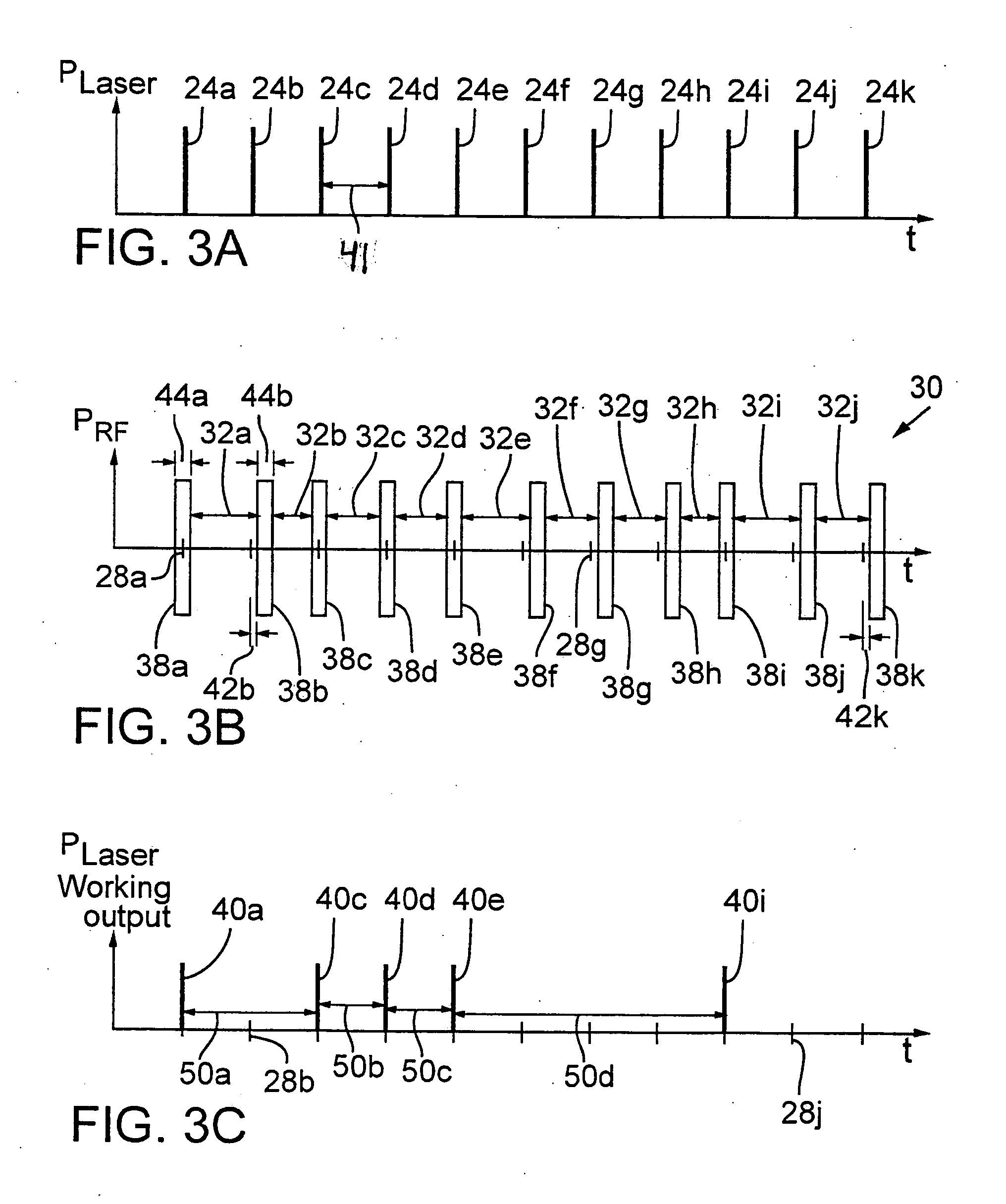
[0039]FIGS. 3A-3C (collectively, FIG. 3) show corresponding timing graphs of laser outputs 24a-24k (collectively, laser outputs 24), RF pulses 38a-38k (collectively, RF pulses 38) applied to prior art AOM 10, and working laser outputs 40a, 40c, 40d, 40e, and 40i (collectively, working laser outputs 40). In particular, FIG. 3A shows laser outputs 24a-24k that are emitted by a laser (not shown) at a constant repetition rate and separated by substantially identical laser output intervals 41. In typical embodiments, the laser output repetition rate may range from about 1 KHz up to about 500 KHz. Exemplary laser output repetition rates range from about 25 KHz to greater than about 100 KHz. For link processing embodiments, each of working laser outputs 40 preferably includes a single laser pulse having a multiple nanosecond pulse width. However, skilled persons will recognize that each of working laser outputs 40 may include a burst of one or more laser pulses each having an ultrashort pu...


PUM

PropertyMeasurementUnit
wavelengthsaaaaaaaaaa
energy wavelengthsaaaaaaaaaa
wavelengthsaaaaaaaaaa

Abstract

A laser processes a workpiece with laser pulses delivered at random time intervals and at substantially constant energy levels by characterizing the laser cavity discharge behavior and utilizing that information for adjusting dummy pulse time periods to compensate for the energy errors. Dummy pulses are laser pulses that are blocked from reaching a workpiece. A second way for providing constant pulse energies employs an AOM for varying amounts of laser energy passed to the workpiece. A third way of providing constant pulse energies entails extending the pulse period of selected pulses to allow additional laser cavity charging time whenever a dummy pulse is initiated.

Description

RELATED APPLICATION [0001] This application is a continuation-in-part of U.S. patent application Ser. No. 10 / 611,798, filed Jun. 30, 2003, for LASER PULSE PICKING EMPLOYING CONTROLLED AOM LOADING.TECHNICAL FIELD [0002] This invention relates to lasers and, more particularly, to a method and an apparatus for providing high repetition rate, stable energy laser pulses on demand with a load controlled acousto-optic modulator (“AOM”) to minimize distortion of the quality or positional accuracy of the laser beam. BACKGROUND OF THE INVENTION [0003] Lasers are widely employed in a variety of R & D operations including spectroscopic and biotech study and industrial operations including inspecting, processing, and micromachining a variety of electronic materials and substrates. For example, to repair a dynamic random access memory (“DRAM”), laser pulses are used to sever electrically conductive links to disconnect faulty memory cells from a DRAM device, and then to activate redundant memory c...

Claims


Application Information

Patent Timeline
12 May 2005
Publication
US20050100062A1
CPC
B23K26/063; B23K26/0635; B23K26/0853; B23K26/4075; B23K2201/36; H01S3/10; H05K3/0038; H01S3/10069
Inventors
GRANT, KEITH; STONE, STEVE