Micro-mechanical capacitive inductive sensor for wireless detection of relative or absolute pressure

a capacitive inductive sensor and wireless detection technology, applied in the field of capacitive pressure sensors, can solve the problems of inferior resistivity, significant resistive loss in the coil, and limit the quality factor of the coil, so as to reduce the overall size of the device

Inactive Publication Date: 2005-05-19
FOR NAT RES INITIATIVES
View PDF13 Cites 30 Cited by
  • Summary
  • Abstract
  • Description
  • Claims
  • Application Information

AI Technical Summary

Benefits of technology

[0006] It is, therefore, an object of the present invention to provide a complete capacitor / inductor pressure sensing structure which has an improved overall resonance quality factor compared to prior art devices.
[0007] It is another object of the present invention to realize such improvement by increasing the quality factor of the inductor by increasing the inductance and decreasing the resistive loss in the inductor.
[0008] It is a further object of the present invention to achieve the increase in inductance while at same time reducing the overall dimensions of the pressure sensing structure.
[0010] It is still a further object of the present invention to provide the pressure sensing structure in a simple hermetically sealed assembly, in which only the diaphragm is exposed to the environment.
[0011] It is a further object of this invention to realize the pressure sensing structure and assembly in a manner that minimizes fabrication cost and manufacturing complexity.
[0015] The present invention is comprised of an LTCC substrate, in which a high quality inductor and fixed counter electrode have been formed, and a second substrate in which a pressure sensitive diaphragm has been formed. When the substrates are bonded together, the diaphragm and fixed counter electrode form a pressure sensitive capacitor connected internally to a coil. The inductor coil is implemented in several layers in the LTTC substrate directly under the fixed counter electrode and movable diaphragm to reduce the overall size of the device.

Problems solved by technology

Unfortunately, in prior art devices based on planar coils, as shown in FIG. 1, there are several limitations that affect the quality factor of the coil.
Electroplated metals are known to have inferior resistivity compared to metals deposited by other means, which therefore results in significant resistive losses in the coil 9.

Method used


Image

  • Micro-mechanical capacitive inductive sensor for wireless detection of relative or absolute pressure
  • Micro-mechanical capacitive inductive sensor for wireless detection of relative or absolute pressure
  • Micro-mechanical capacitive inductive sensor for wireless detection of relative or absolute pressure

Examples


Embodiment Construction

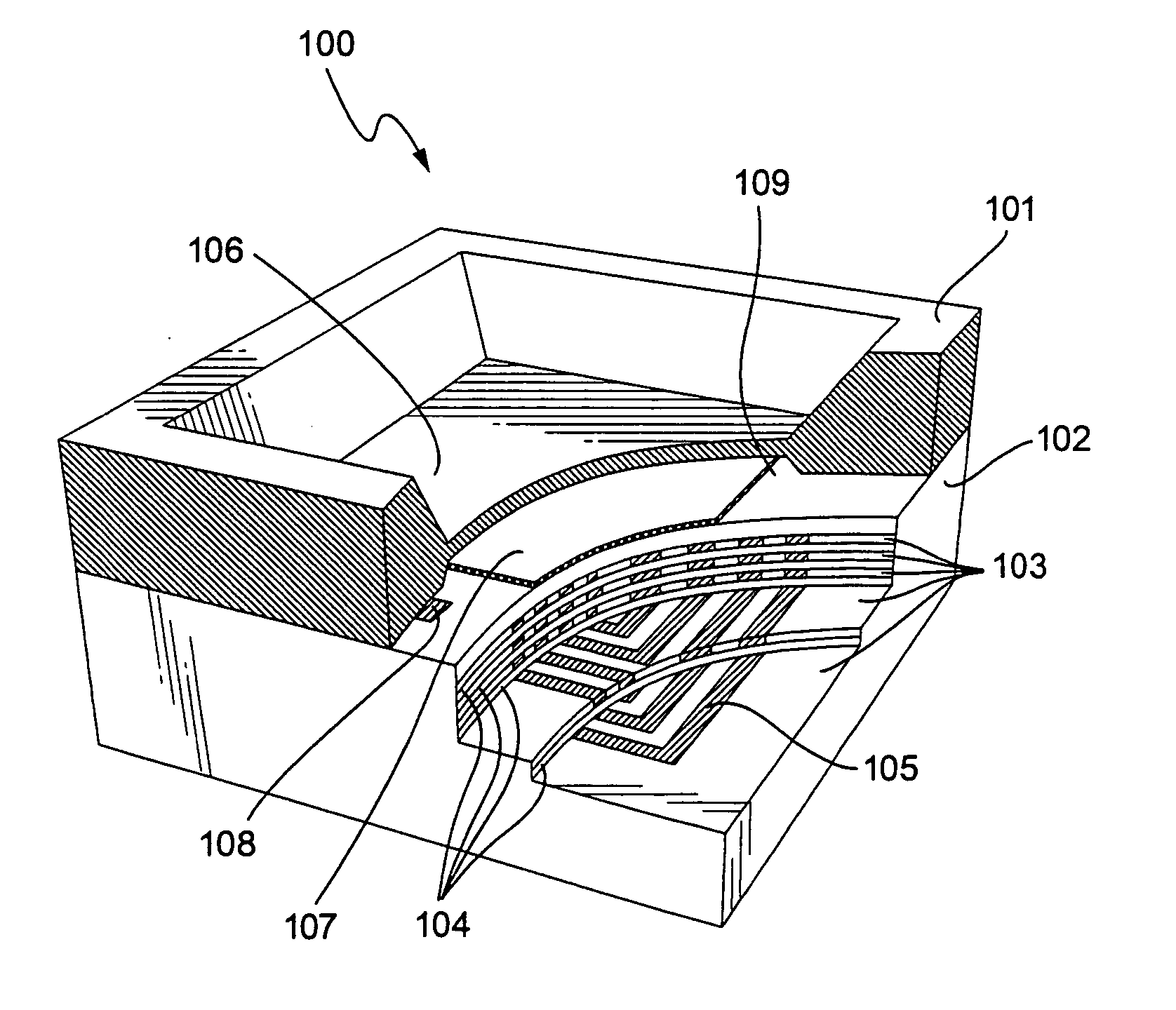
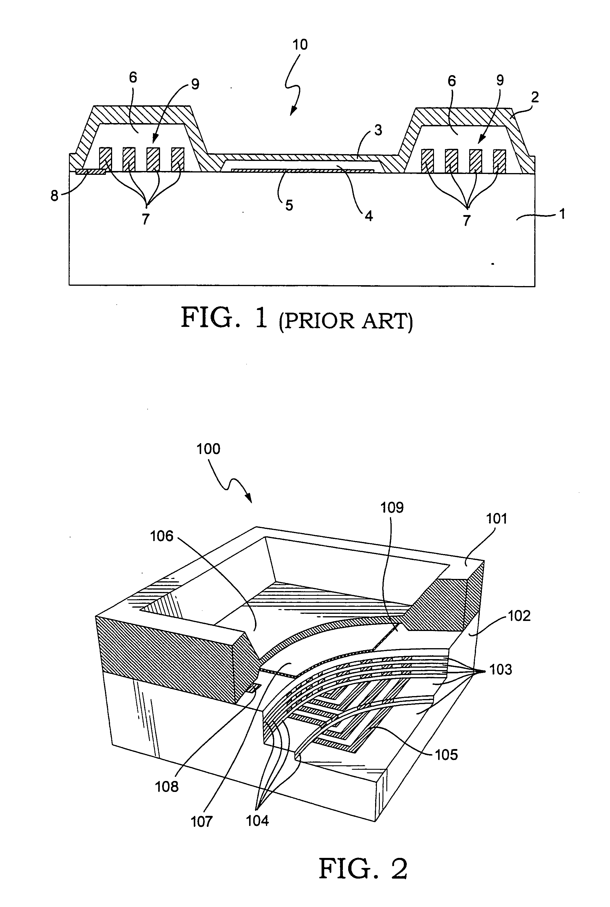
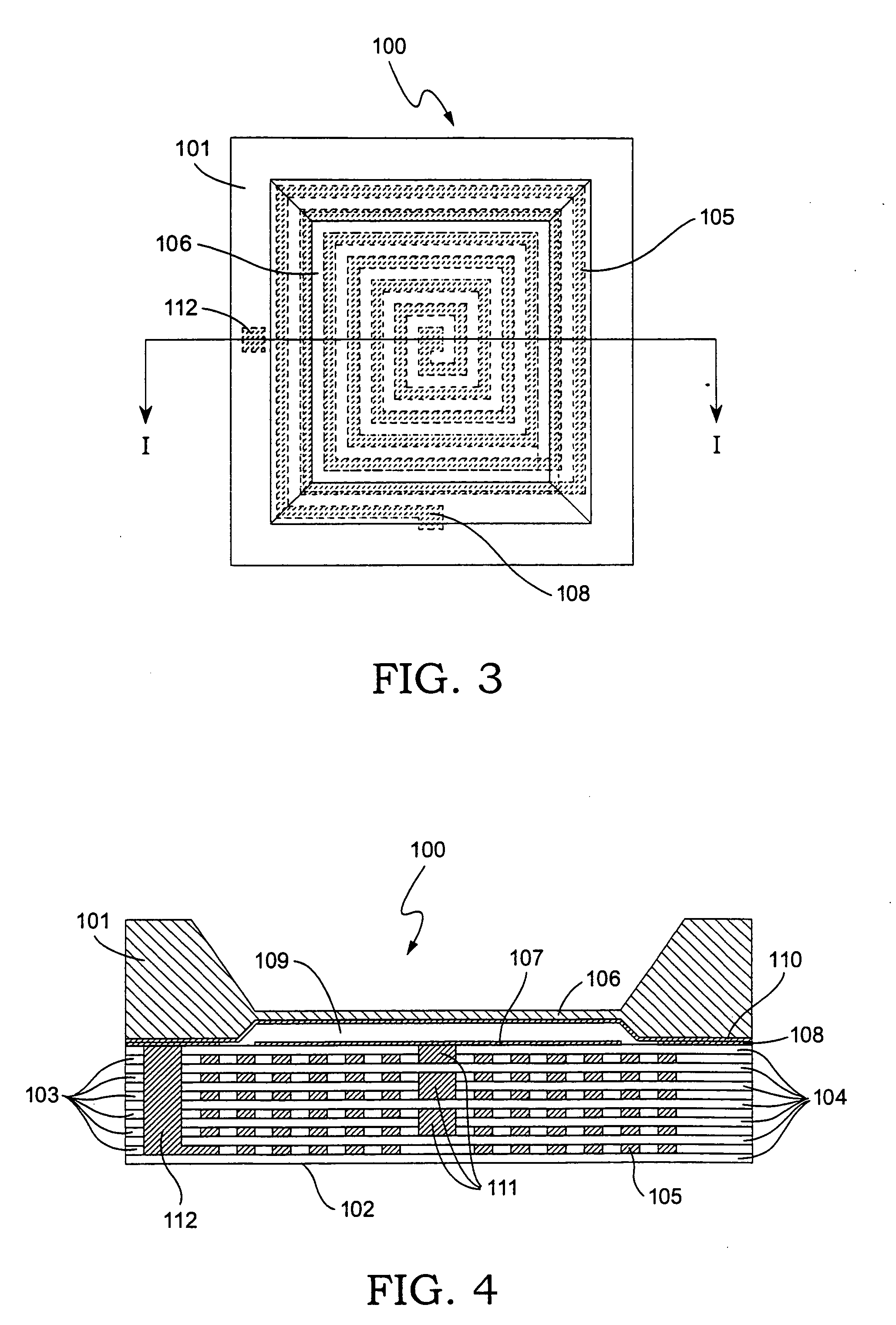
[0023] One embodiment of a pressure sensing structure according to the present invention is shown in perspective view in FIG. 2, top plan view in FIG. 3, and cross-sectional view in FIG. 4. The pressure sensing structure 100 consists of a substrate 101, containing a thin diaphragm 106, and a second hybrid substrate 102, in which an electrical inductor 105 has been formed. The two substrates 101 and 102 are bonded together and hermetically sealed to form a cavity 109. Any deflection of the diaphragm 106 in response to a pressure differential between the sealed cavity and the exterior atmosphere results in a change of capacitance between a fixed counter electrode 107 and a conductive layer 110 on diaphragm 106. Inductor 105 is connected to the fixed electrode 107 by via 111, shown in FIG. 4, and to a conductive layer 110 on diaphragm 106 through via 112 and conductive layer 108. The inductor 105 is formed in multi layered hybrid substrate 102. A preferred technology for the implementa...


PUM

PropertyMeasurementUnit
surface roughnessaaaaaaaaaa
capacitanceaaaaaaaaaa
conductiveaaaaaaaaaa

Abstract

A micro-mechanical pressure transducer is disclosed in which a capacitive transducer structure is integrated with an inductor coil to form a LC tank circuit, resonance frequency of which may be detected remotely by imposing an electromagnetic field on the transducer. The capacitive transducer structure comprises a conductive movable diaphragm, a fixed counter electrode, and a predetermined air gap between said diaphragm and electrode. The diaphragm deflects in response to an applied pressure differential, leading to a change of capacitance in the structure and hence a shift of resonance frequency of the LC tank circuit. The resonance frequency of the LC circuit can be remotely detected by measuring and determining the corresponding peak in electromagnetic impedance of the transducer.

Description

[0001] This application claims the benefit of Provisional Application No. 60 / 389,292, filed Jun. 18, 2002, the entire contents of which is hereby incorporated by reference in this applicationFIELD OF THE INVENTION [0002] The present invention pertains to the field of pressure sensors, and more specifically to capacitive pressure sensors, remote sensing, and to the fields of micro fabrication and micro electro mechanical systems (MEMS). BACKGROUND OF THE INVENTION [0003] Pressure sensors made by micro machining methods are well known and considered one of the most mature applications for MEMS technology. Since the early 1970's, pressure sensitive diaphragms have been formed from silicon substrates, the deflection of which have been detected by optical, piezoresistive, piezoelectric or capacitive means. So far, the most significant detection method used for commercial applications has been piezoresistive detection, which is convenient to implement since single crystal silicon is an in...

Claims


Application Information

Patent Timeline
Patent Type & Authority Applications(United States)
IPC IPC(8): G01L9/00
CPCG01L9/0073
Inventor PEDERSEN, MICHAELOZGUR, MEHMETHUFF, MICHAEL A.
Owner FOR NAT RES INITIATIVES
Why Eureka
Try Eureka