Charge barrier flow-through capacitor

a flow-through capacitor and charge barrier technology, applied in the field of flow-through capacitors, can solve the problems of reducing the efficiency of flow-through capacitors of the prior art, reducing the efficiency of flow-through capacitors, and causing double deleterious effects, and achieves energy-efficient purification of concentrated fluids, low resistance-capacitance, and large increase in ionic efficiency

Inactive Publication Date: 2005-05-19
VOLTEA
View PDF38 Cites 79 Cited by
  • Summary
  • Abstract
  • Description
  • Claims
  • Application Information

AI Technical Summary

Benefits of technology

[0010] As used herein, the term “charge barrier” refers to a layer of material which is permeable or semipermeable and is capable of holding an electric charge. Pore ions are retained, or trapped, on the side of the charge barrier towards which the like-charged ion, or coion, migrates. This charge barrier material may be a laminate which has a conductive low resistance-capacitance (RC) time constant, an electrode material, or may be a permselective, i.e., semipermeable, membrane, for example a cation or anion permselective material, such as a cation exchange or anion exchange membrane. The charge barrier may have a single polarity, two polarities, or may be bipolar. Generally, a charge barrier functions by forming a concentrated layer of ions. The effect of forming a concentrated layer of ions is what balances out, or compensates for, the losses ordinarily associated with pore volume ions. This effect allows a large increase in ionic efficiency, which in turn allows energy efficient purification of concentrated fluids.

Problems solved by technology

One disadvantage of prior art systems is the energy loss resulting from using multiple compartment layers between electrodes, thereby creating an electrical resistance.
However, flow-through capacitors of the prior art become energy inefficient and impractical at high ion or contaminant concentrations.
This has a doubly deleterious effect.
This amount of charge-holding capacitance is therefore unavailable for purification of ions from the feed water purification stream.
This effect becomes worse with increased concentration.
This puts an upper practical limit on the economy of the flow-through capacitor, typically in the range of approximately 2500 to 6000 parts per million (ppm).
Beyond 6000 ppm, the energy usage required is typically more than 1 joule per coulomb of dissolved ions, making prior art flow-through capacitors too energy intensive to be practical.
Seawater, which has ion concentrations of approximately 35,000 ppm, becomes impractical to deionize due to energy inefficiency caused by these pore volume losses.
Pore volume losses occur at all concentrations but get worse at higher concentrations.
Another way to describe pore volume losses is that they cause diminished ionic efficiency.

Method used


Image

  • Charge barrier flow-through capacitor
  • Charge barrier flow-through capacitor
  • Charge barrier flow-through capacitor

Examples


example 1

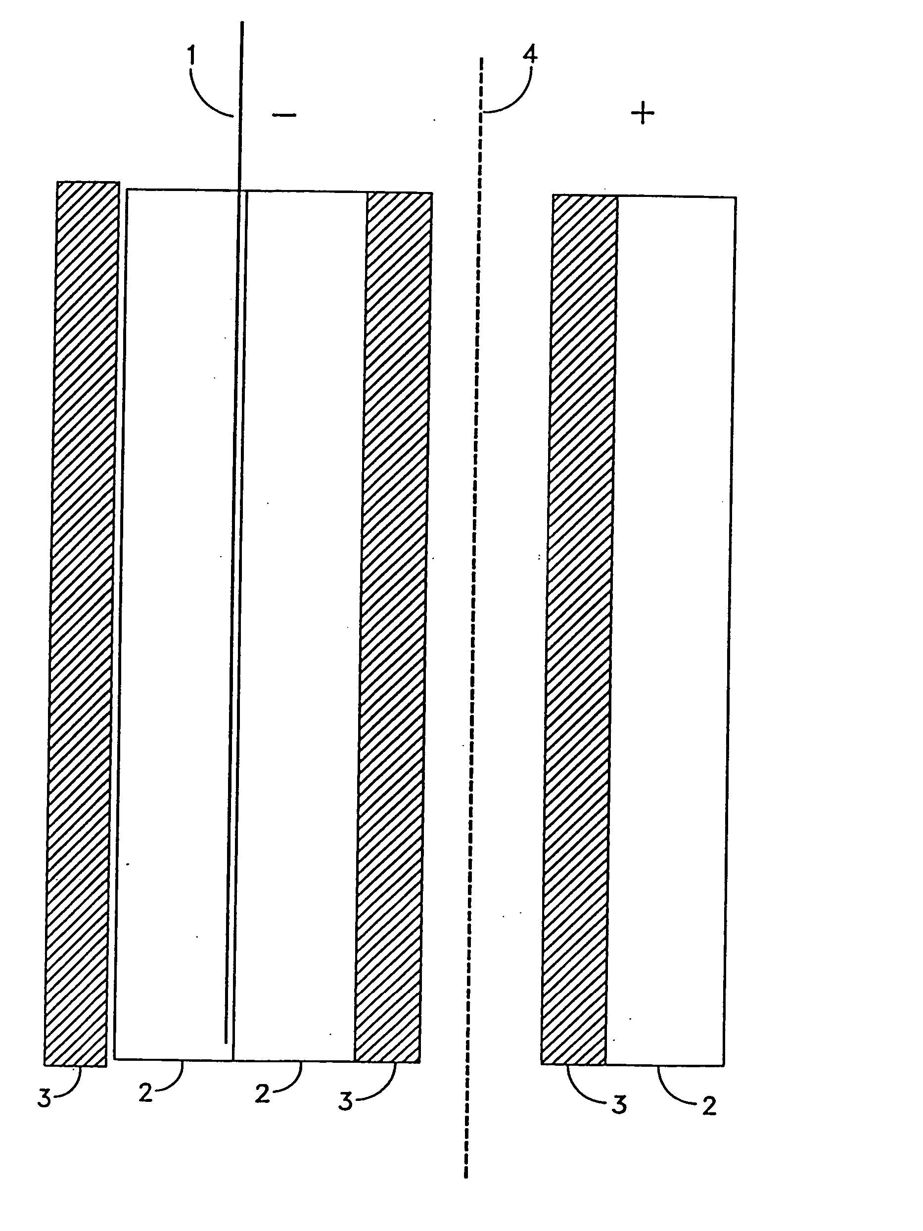
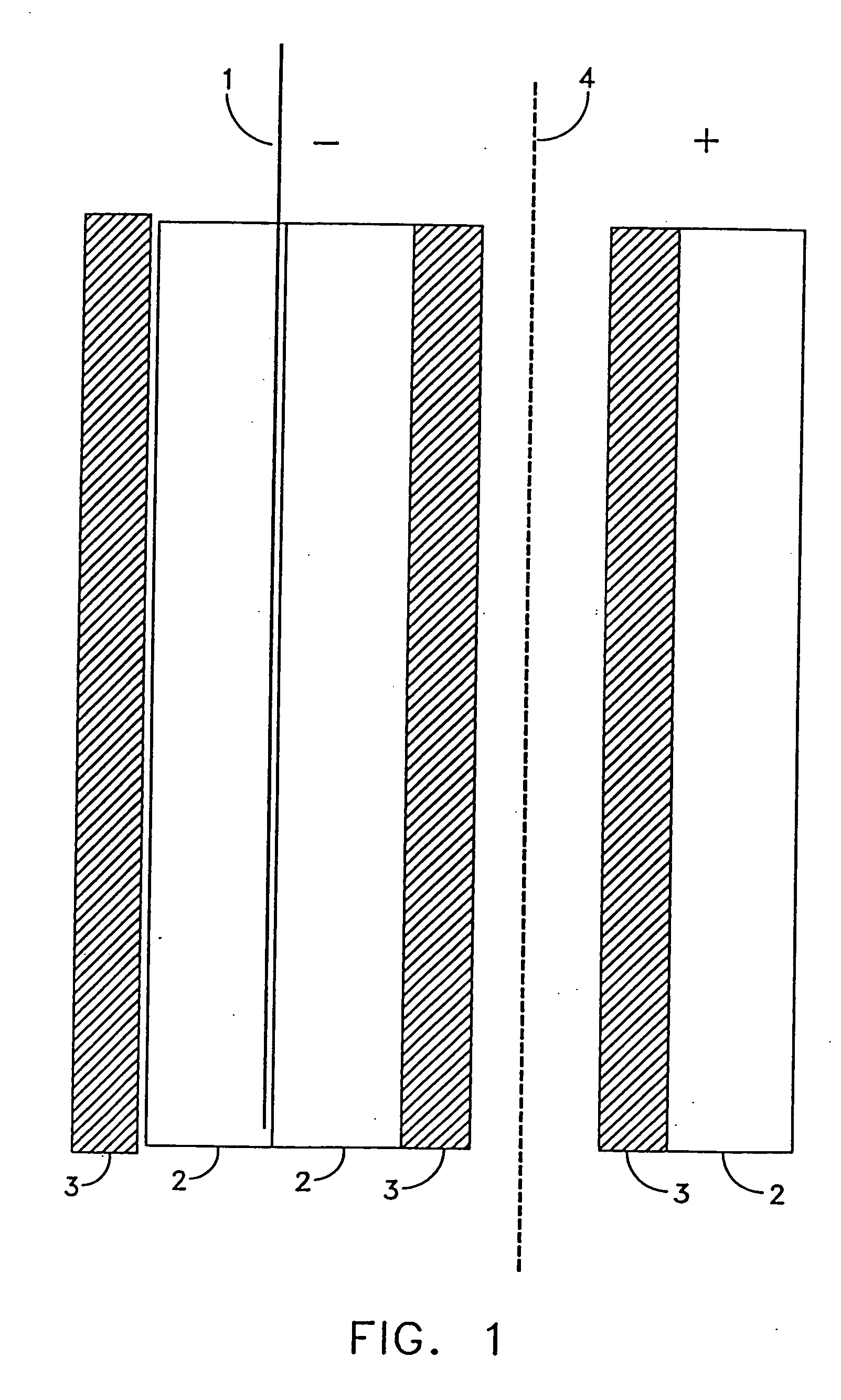
[0093] The flow-through capacitor of FIG. 10 is prepared using electrodes composed of 95% carbon black and 5% of a polymer PTFE or similar polymer. Charge barriers are composed of permselctive membranes. In the capacitor of FIG. 10, a cation exchange membrane, such as RAIPORETM™ 1010 membrane with fixed benzyl sulfonic acid groups, is placed touching and adjacent to the negative electrode. An anion exchange membrane, in this case, a RAIPORETM™ 1030 membrane with fixed phenyl tetramethyl ammonium groups, is placed touching and adjacent to the positive electrode. A 0.003 inch thick filtration netting is placed between the two oppositely-charged permselective membranes and to form the flow path. The capacitor is charged at constant current, up to a voltage limit of 1 volt. Seawater flowing between the membranes is purified to 12%. In order to reach a purity of 99%, several capacitors are used in series or stages with series flow to reduce the salinity to 6000 ppm. An additional flow-th...

example 2

[0094] The flow-through capacitor of Example 1 is used at a flow rate of less than 1 ml / minute / gram of carbon, for example, 0.1 ml / minute / gram of carbon, to achieve greater than 90% purification of a 35,000 ppm salt solution.

example 3

[0095] The flow-through capacitor of Example 1 is coupled through an inductor in order to recover energy during discharge. This energy is used to charge a second capacitor during its purification cycle. Maximum charging voltage of both capacitors is kept below 0.7 volts, in order to minimize energy usage. Capacitors may be charged either at constant voltage, constant current, or at constantly increasing voltage, or constantly increasing current. Optionally, capacitors may be charged in series in, order to increase the voltage for maximum energy recovery and power supply efficiency.


PUM

PropertyMeasurementUnit
porosityaaaaaaaaaa
thickaaaaaaaaaa
thickaaaaaaaaaa

Abstract

Flow-through capacitors are provided with one or more charge barrier layers. Ions trapped in the pore volume of flow-through capacitors cause inefficiencies as these ions are expelled during the charge cycle into the purification path. A charge barrier layer holds these pore volume ions to one side of a desired flow stream, thereby increasing the efficiency with which the flow-through capacitor purifies or concentrates ions.

Description

REFERENCE TO PRIOR APPLICATION [0001] This application is a continuation of U.S. Ser. No. 10 / 772,206, filed Feb. 4, 2004, which is a continuation of U.S. Ser. No. 10 / 015,120, filed Oct. 26, 2001, now U.S. Pat. No. 6,709,560 B2, issued Mar. 23, 2004, which is a continuation-in-part of PCT / US01 / 12641, with an international filing date of Apr. 18, 2001, designated to be published in English under PCT Article 21(2), and hereby incorporated by reference.GOVERNMENT CONTRACT [0002] This invention was funded under contract with the United States Defense, Advanced Research Projects Agency (DARPA), under Contract No. DAAD 19-99-C-0033. The United States government may have certain rights in the invention.FIELD OF THE INVENTION [0003] The invention relates to a flow-through capacitor for deionizing or decontaminating a fluid. BACKGROUND OF THE INVENTION [0004] The invention relates to flow-through capacitors for deionizing solutions, e.g., aqueous solutions, with improved operation at concentr...

Claims


Application Information

Patent Timeline
Patent Type & Authority Applications(United States)
IPC IPC(8): C02F1/469
CPCC02F1/008C02F1/469C02F1/4691C02F2103/08C02F2201/005C02F2201/46C02F2209/001C02F2209/003C02F2209/005C02F2209/05C02F1/4695C02F2201/46145
Inventor ANDELMAN, MARC D.WALKER, GREGORY S.
Owner VOLTEA
Why Eureka
Try Eureka