User terminal antenna arrangement for multiple-input multiple-output communications

a multi-output, multi-input technology, applied in the direction of polarised antenna unit combinations, collapsible antenna means, polarisation/directional diversity, etc., to achieve the effect of simple structure, good omnidirectional coverage, and easy installation

Inactive Publication Date: 2005-05-19
APPLE INC
View PDF7 Cites 7 Cited by
  • Summary
  • Abstract
  • Description
  • Claims
  • Application Information

AI Technical Summary

Benefits of technology

[0021] Preferably, said first pair of antennas are selected from monopoles and umbrella monopoles. This provides the advantage that the antennas are of a simple structure which is easy to install. Also, the antennas provide good omnidirectional coverage in an azimuth plane. Umbrella monopoles are advantageous in situations where space is restricted. These are a type of top-loaded monopole. Top-loaded monopoles are preferred because these have a 2D structure which can be used to achieve a slim-line antenna structure that is suitable for PDAs. However, normal mode spiral structures can also be used provided sufficient depth is available for such 3D structures.
[0022] In a preferred embodiment one of the second pair of antennas is a slot. This provides the advantage that a simple antenna structure that is easy to install is provided. Also the radiation pattern characteristics are similar to that for the monopole structure mentioned above but with the opposite polarisation. The slot can be shortened to save space, for example, by forming a dumbbell.
[0023] Preferably the other of the second pair of antennas is a monopole and is arranged to protrude from the user terminal in use. This provides the advantage that good omnidirectional coverage in an azimuth plane is achieved. Also the antenna structure is simple and can easily be arranged to fold away against the body of the user terminal or to retract into the body of the user terminal when not in use.
[0024] In another embodiment the antenna arrangement, when used as par...

Problems solved by technology

These systems involve using a plurality of antennas on both the transmitter and receiver and the problem of how to accommodate such structures in user terminals, which are often requ...

Method used


Image

  • User terminal antenna arrangement for multiple-input multiple-output communications
  • User terminal antenna arrangement for multiple-input multiple-output communications
  • User terminal antenna arrangement for multiple-input multiple-output communications

Examples


Embodiment Construction

[0048] Embodiments of the present invention are described below by way of example only. These examples represent the best ways of putting the invention into practice that are currently known to the Applicant although they are not the only ways in which this could be achieved.

[0049] The term “directional antenna” is used to refer to an antenna which has a pattern that is not omnidirectional and which has significant directive gain in a particular direction.

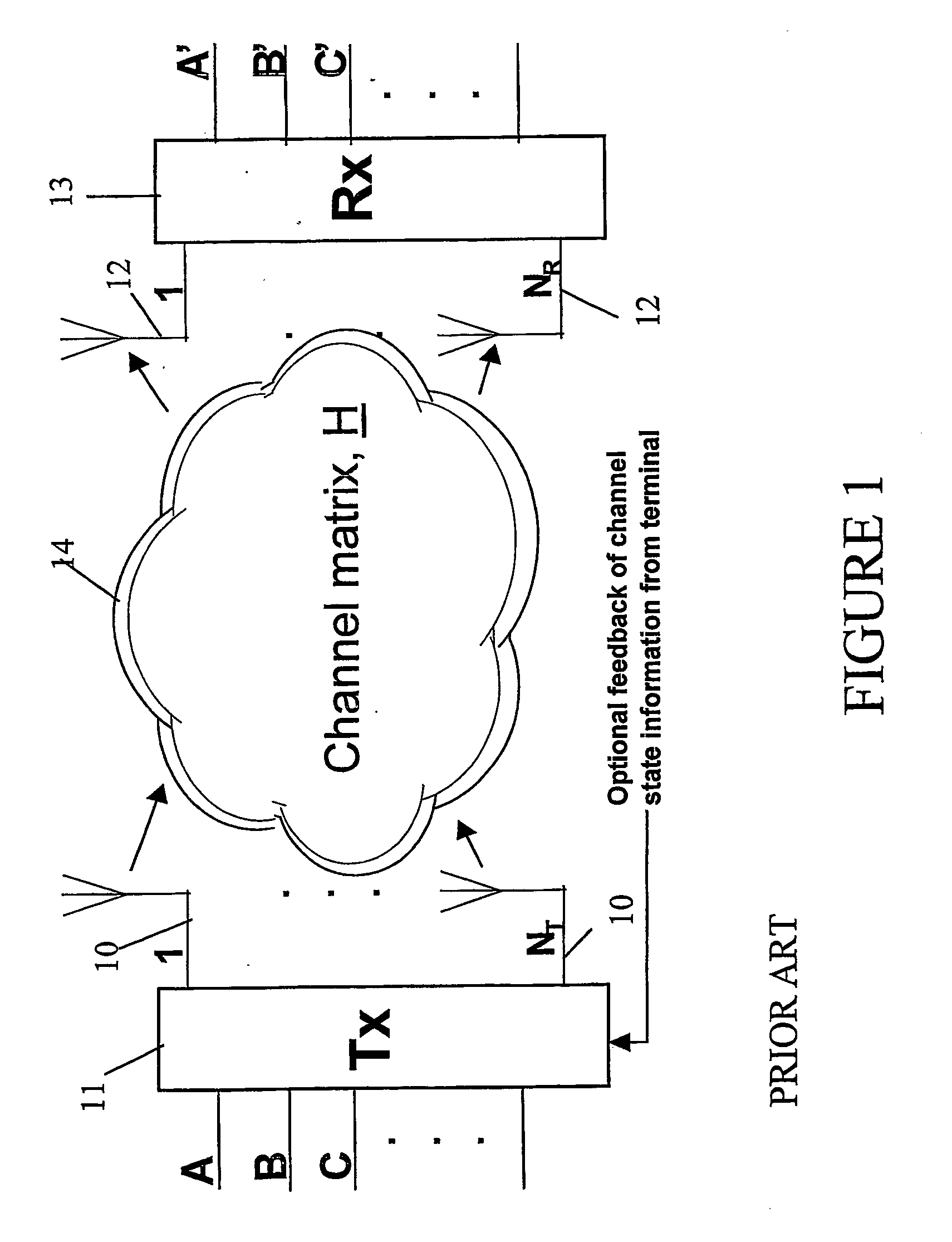
[0050] A MIMO wireless communication system (see FIG. 1) is one which comprises a plurality of antennas 10 at the transmitter 11 and a plurality of antennas 12 at the receiver 13. The antennas 10, 12 are employed in a multi-path rich environment such that due to the presence of various scattering objects (buildings, cars, hills, etc.) in the environment, each signal experiences multipath propagation. Thus a cloud shape 14 is shown in FIG. 1 to represent the scattered signals between the transmit and receive antennas. User data is...


PUM


Abstract

Multiple input multiple output (MIMO) systems are able to provide wireless communications at increased data rates. These systems involve using a plurality of antennas on both the transmitter and receiver and the problem of how to accommodate such structures in user terminals, which are often required to be hand held then arises. An antenna arrangement which is suitable for MIMO communications and which can be incorporated into a user terminal such as a personal digital assistant (PDA) is described. A pair of co-polarised umbrella monopoles and a slot antenna are incorporated into a flap which extends at approximately 90° to the body of the PDA. A fourth monopole is mounted and protrudes from the PDA itself.

Description

FIELD OF THE INVENTION [0001] The present invention relates to an antenna arrangement suitable for user terminal multiple-input multiple-output radio communications systems. BACKGROUND TO THE INVENTION [0002] The demand for wireless communication systems has grown steadily over recent decades, and has included several technological jumps over this time, particularly in the area of cellular and wireless local area network (WLAN) communication systems. Analogue cellular phones have been replaced with digital handsets using for example GSM and CDMA technologies, and so called third generation systems such as UMTS are now being introduced. Similarly WLAN technologies such as HyperLan and IEEE 802.11b are also being introduced. The number of users continues to increase and data traffic is now becoming an important part of the wireless network. Both of these factors mean that it is important for operators to look for methods of increasing the capacity of their networks to meet future dema...

Claims


Application Information

Patent Timeline
IPC IPC(8): H01Q1/08H01Q1/22H01Q1/24H01Q1/38H01Q9/44H01Q13/10H01Q21/24H01Q21/28H04B7/10
CPCH01Q1/084H01Q1/243H01Q1/38H01Q9/44H04B7/10H01Q13/106H01Q21/24H01Q21/28H01Q25/001H01Q13/10
Inventor SMITH, MARTINPOWER, DAWNAMOS, SONYAPERROTT, ROGER
Owner APPLE INC
Why Eureka
Try Eureka