Magnetic cell and magnetic memory

a magnetic memory and cell technology, applied in the field of magnetic memory and cell, can solve the problems of insufficient generated magnetic field, difficulty in conducting localization, and noticeable effect, and achieve the effect of reducing fluctuation and high developing rate of mr characteristics

Inactive Publication Date: 2005-05-19
KK TOSHIBA
View PDF2 Cites 42 Cited by
  • Summary
  • Abstract
  • Description
  • Claims
  • Application Information

AI Technical Summary

Benefits of technology

[0011] In view of the above circumstances, the present invention has been made, and an object thereof is to provide a magnetic cell having a high developing rate of MR characteristics and a reduced fluctuation without causing element falling-down and a magnetic memory having the same.
[0012] A magnetic memory according a first aspect of the present invention includes: a lower electrode; an electrically conductive pillar formed on the lower electrode; a magnetoresistance effect film having at least two ferromagnetic layers formed on the electrically conductive pillar and an intermediate layer provided between the ferromagnetic layers; an upper electrode formed on the magnetoresistance effect film; a support layer formed from at least one metal directly on a side face of the electrically conductive pillar or via an insulating layer; and a current diffusion preventing layer provided between the support layer and the lower electrode, a height of the electrically conductive pillar, a thickness of the current diffusion preventing layer, and a thickness of the support layer satisfying relationships of h>t⁢ ⁢1+t⁢ ⁢2>3030+L×h

Problems solved by technology

However, since the magnetic field is fundamentally provided with a property of expanding in space, it is difficult to conduct localization.
According to further fineness of a bit or a memory cell in size, when a specific bit or memory cell is selected and its magnetizing direction is controlled, such a problem about “cross talk” where magnetic field influences an adjacent bit or memory cell occurs noticeably.
When a magnetic field generating source is made small for achieving localization of magnetic field, there arises another problem that a sufficient generated magnetic field can not be obtained.
In these direct etching processes, however, when a much fine

Method used


Image

  • Magnetic cell and magnetic memory
  • Magnetic cell and magnetic memory
  • Magnetic cell and magnetic memory

Examples


first embodiment

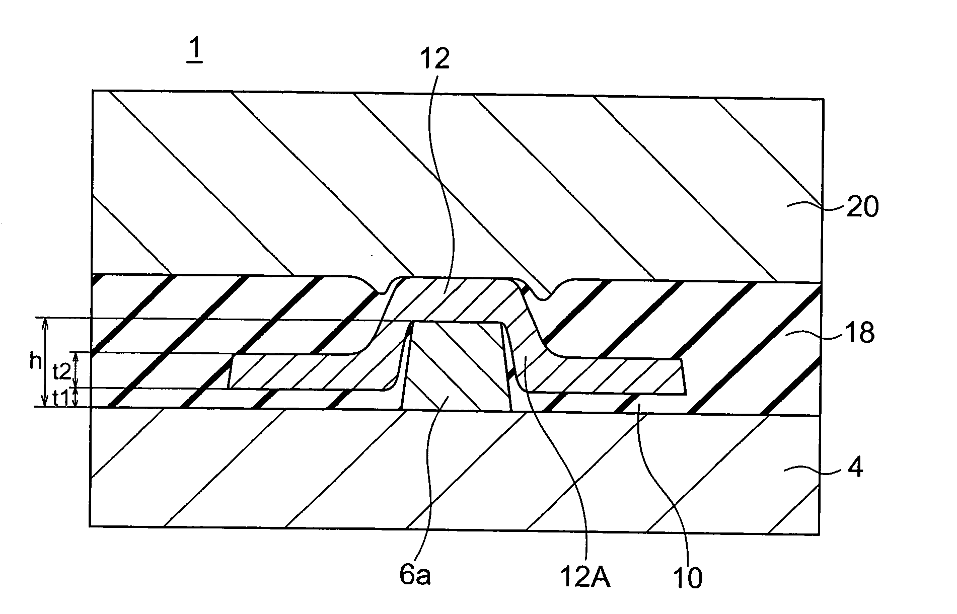
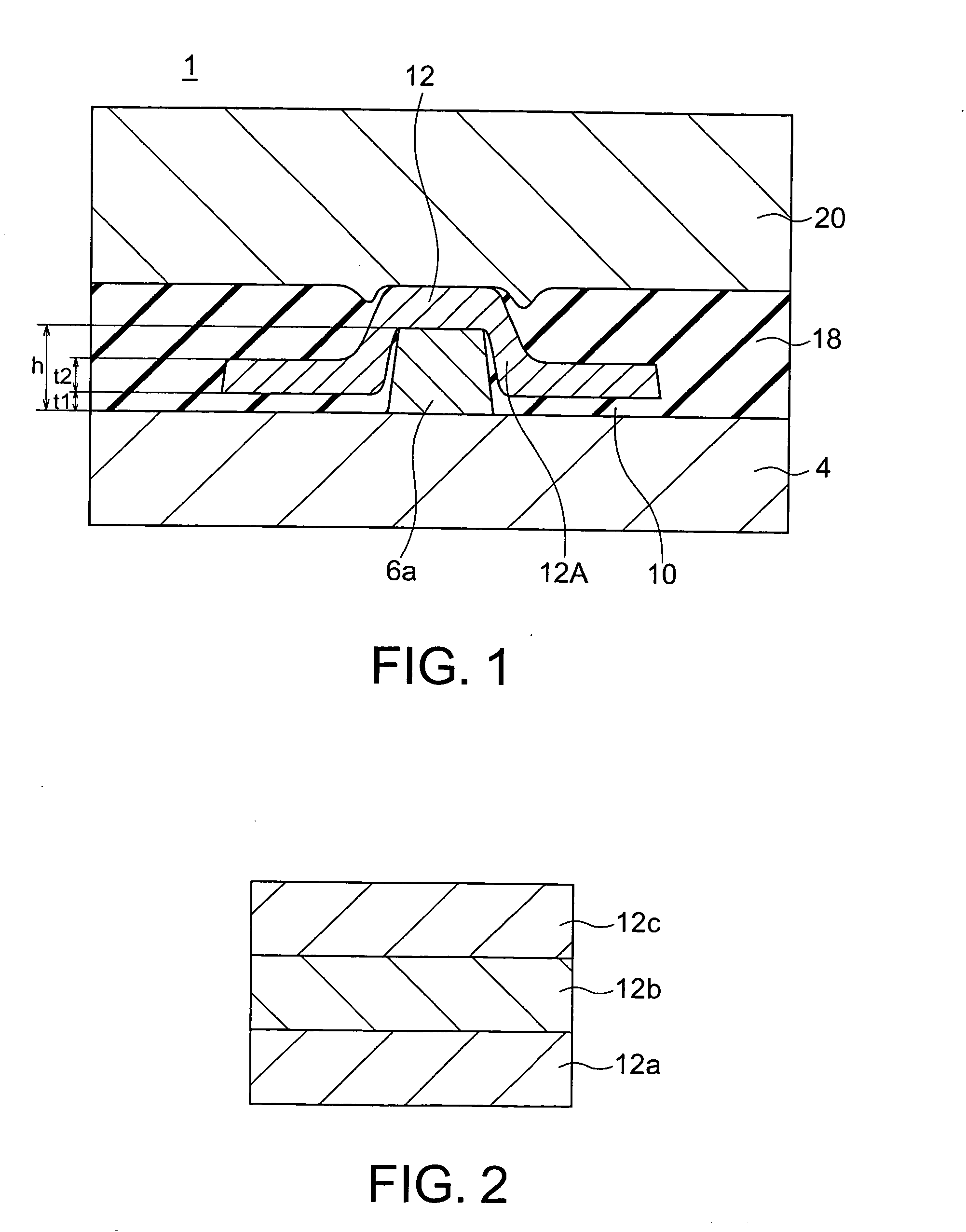
[0051] A constitution of a magnetic cell according to a first embodiment of the present invention is shown in FIG. 1. A magnetic cell according to the embodiment is provided with a lower electrode 4, an electrically conductive pillar 6a formed on the lower electrode 4, a magnetoresistance effect film 12 (hereinafter, also called “MR film 12”) formed on the electrically conductive pillar 6a, an upper electrode 20 formed on the MR film 12, a support layer 12A formed on a side face of the electrically conductive pillar 6a, and a current diffusion preventing layer 10 formed between the support layer 12A and the lower electrode 4.

[0052] The support layer 12A is provided on a side face of the electrically conductive pillar 6a via an insulating film 10. In this embodiment, when a height of the electrically conductive pillar 6a is represented as h, a thickness of the current diffusion preventing layer 10 is represented as t1, a thickness of the support layer 12a is represented as t2 and a ...

modified embodiment

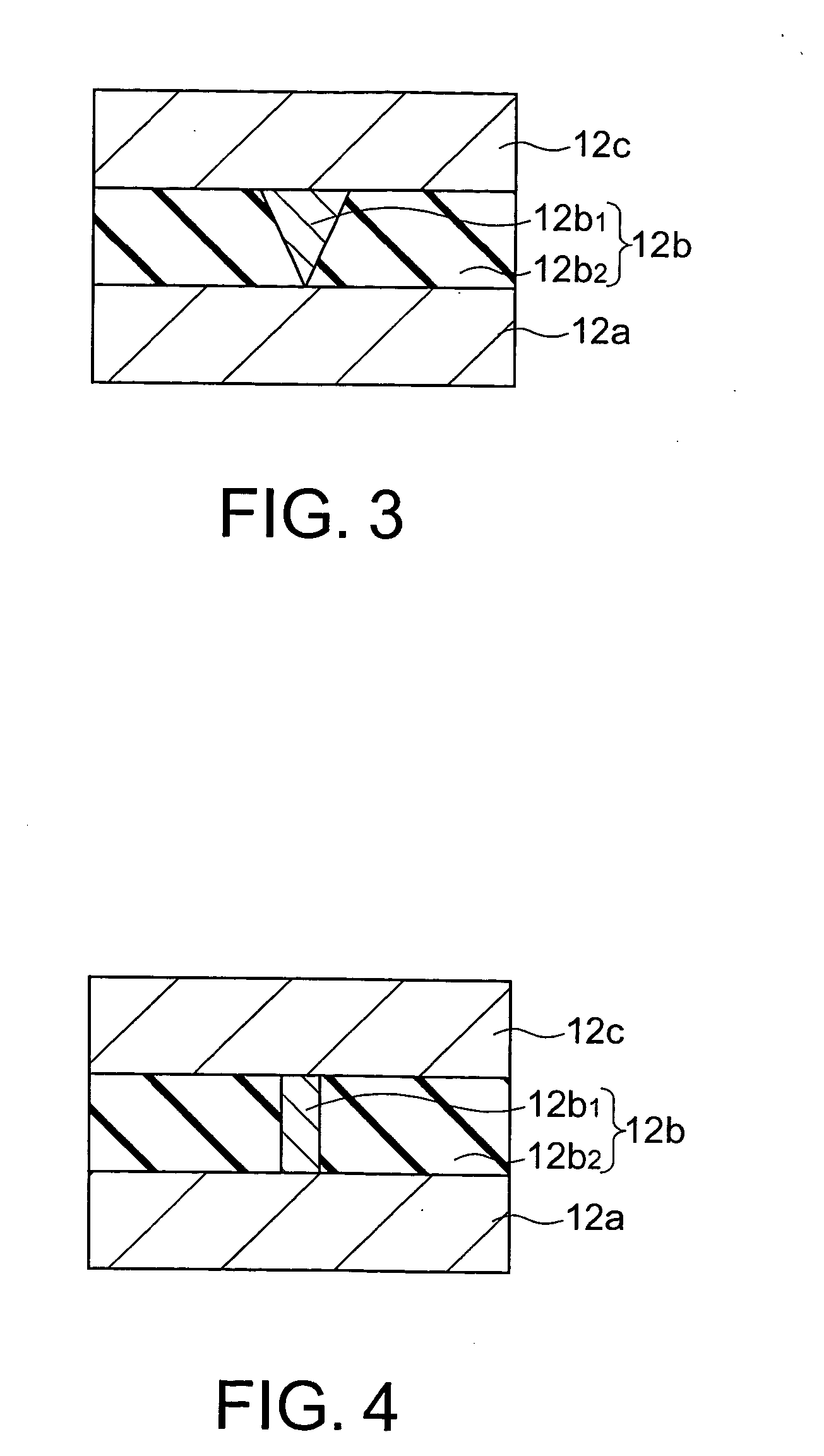
[0071] As shown in FIG. 3, for example, regarding the intermediate layer, “a point contact”, namely, a fine contact 12b1 having a contacting area of 100 nm2 or less is provided in an intermediate layer 12b, and a soft magnetic layer 12a and a hard magnetic layer 12c are electrically connected to each other via the fine contact point 12b1. The fine contact point 12b1 can be formed such that one portions of the hard magnetic layer 12c and the soft magnetic layer 12a extend or it can be formed of such rare metal as copper (Cu), silver (Ag) or gold (Au), or alloy containing at least one these rare metals. In the intermediate layer 12b, a periphery of the fine contact point 12b1 is covered with an insulator 12b2 such as silicon oxide (SiOx) or aluminum oxide (AlOx).

[0072] As shown in FIG. 3, the fine contact point 12b1 may have a cone-shaped section, or it may have a pillar-shaped section, as shown in FIG. 4. Further, as shown in FIGS. 5 and 6, a plurality of fine contact points 12b1 ma...

second embodiment

[0092] Next, a magnetic cell according to a second embodiment of the present invention will be explained with reference to FIG. 18 to FIG. 20. FIGS. 18 to 20 are sectional views showing steps of manufacturing a magnetic cell according to this embodiment. The magnetic cell according to this embodiment has a constitution that the lower electrode 4 and the electrically conductive pillar 6a are integrally formed using the same material in the magnetic cell according to the first embodiment shown in FIG. 1. A constitution of the magnetic cell according to the embodiment will be explained with reference to FIGS. 18 to 20 which are sectional views for showing manufacturing steps.

[0093] As shown in FIG. 18, first, an electrode layer 5 was formed on a substrate 2 by forming Ta (5) / Cu—Ag (400) / Ta (10) on the substrate 2 in this order from the bottom by using sputter process and it was planarized and smoothed by CMP. A blanketed numeral denotes a film thickness (nm). An electrode terminal por...


PUM


Abstract

It is possible to provide a magnetic cell having a high developing rate of MR characteristics and a reduced fluctuation without causing element falling-down and a magnetic memory having the same. A magnetic cell includes: a lower electrode; an electrically conductive pillar formed on the lower electrode; a magnetoresistance effect film having at least two ferromagnetic layers formed on the electrically conductive pillar and an intermediate layer provided between the ferromagnetic layers; an upper electrode formed on the magnetoresistance effect film; a support layer formed from at least one metal directly on a side face of the electrically conductive pillar or via an insulating layer; and a current diffusion preventing layer provided between the support layer and the lower electrode, wherein a height of the electrically conductive pillar, a thickness of the current diffusion preventing layer, and a thickness of the support layer satisfy relationships of h>t1+t2>3030+L×h
where h represents the height of the electrically conductive pillar, t1 represents the thickness of the current diffusion preventing layer, t2 represents the thickness of the support layer, and L (nm) represents a length of a short side of the electrically conductive pillar.

Description

CROSS-REFERENCE TO RELATED APPLICATIONS [0001] This application is based upon and claims the benefit of priority from prior Japanese Patent Application No. 2003-338099, filed on Sep. 29, 2003 in Japan, the entire contents of which are incorporated herein by reference. BACKGROUND OF THE INVENTION [0002] 1. Field of the Invention [0003] The present invention relates to a magnetic cell and a magnetic memory. [0004] 2. Related Art [0005] For controlling magnetizing direction of a magnetic body, a method for applying magnetic field on the magnetic body has been conventionally employed. For example, in a hard disc drive, a magnetizing direction of a medium is inverted for performing writing by magnetic field generated from a recording head. In a solid magnetic memory, a current magnetic field generated due to current flowing in a wire provided near a magnetoresistance effect element is applied to a memory cell, so that control on a magnetizing direction of the memory cell is performed. Th...

Claims


Application Information

Patent Timeline
IPC IPC(8): H01L27/105G11C11/15H01L21/8246H01L43/08
CPCG11C11/15
Inventor HANEDA, SHIGERUNAKAMURA, SHIHOOOSAWA, YUUICHI
Owner KK TOSHIBA
Why Eureka
Try Eureka