
Determining stimulation levels for transcranial magnetic stimulation

Active Publication Date: 2005-05-19
NEURONETICS
View PDF29 Cites 67 Cited by
  • Summary
  • Abstract
  • Description
  • Claims
  • Application Information

AI Technical Summary

Benefits of technology

[0012] In a fourth embodiment of the invention, the appropriate stimulation level for TMS studies is determined using techniques other than motor cortex motor threshold methods. There are two parameters that affect proper setting of TMS stimulation levels: cortical depth and level of neuronal excitability. Desired stimulation is proportional to the product of these parameters. This embodiment separately determines each of these two parameters. A localized ultrasound probe may be used to determine the depth of cortical tissue at the treatment site. Alternatively, a localized and specifically designed probe may be used to detect impedance changes or filling factor differences when the probe is placed on the scalp at the desired treatment site. Such a probe may be constructed using a tuned coil and detection circuit that is sensitive to loading differences encountered when different biological tissue is placed in its proximity. The probe may be calibrated by observing impedance or Q factor (i.e. frequency*induct

Problems solved by technology

Both techniques are time consuming and highly dependent upon the skills and training of the practitioner.
It would be advantageous to more directly determine desired levels for stimulating non-motor areas of the brain (e.g. prefrontal cortex); however, such techniques have not yet been developed.
Direct measurement of evoked potential for non-motor areas using EMG techniques has been proposed by Sarah Lisanby, M.D. Unfortunately, direct measurement of evoked potential is not straight-forward since neurons that are directly stimulated are not readily accessible with non-invasive techniques.
Functional magnetic resonance imaging (fMRI) or positron emission tomography may be used to observe levels of neuronal stimulation, but these methods are expensive, would require TMS procedures to be performed at a facility with this equipment, and are logistically impractical for routine clinical TMS therapy.
However, Gliner does not suggest how such a system may be used to detect motor threshold positions and levels and does not suggest correlating induced movement in the patient with a stimulation pulse to find the motor threshold position.
Prior art techniques do not describe methods of separately determining cortical depth and levels of neuronal excitability for the purpose of setting TMS stimulation levels.
The prior art also does not teach techniques of determining TMS stimulation levels by observation and analysis of indirect signals such as EEG and its derivatives.

Method used


Image

  • Determining stimulation levels for transcranial magnetic stimulation
  • Determining stimulation levels for transcranial magnetic stimulation
  • Determining stimulation levels for transcranial magnetic stimulation

Examples


Embodiment Construction

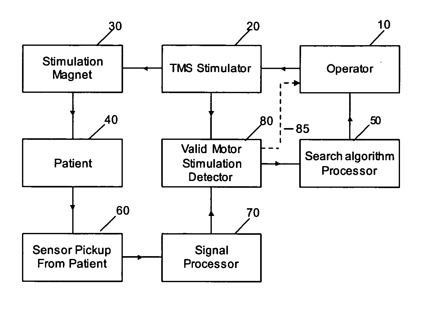
[0018] A detailed description of exemplary embodiments of the present invention will now be described with reference to FIGS. 3 and 4. Although this description provides detailed examples of possible implementations of the present invention, it should be noted that these details are intended to be exemplary and in no way delimit the scope of the invention.

[0019] Prior to TMS, the patient's motor threshold (MT) position is determined and the stimulation position is determined in reference to the MT position. The magnetic flux density, B, produced by the TMS therapy coil is adjusted with the coil positioned at the MT position in order to determine the MT stimulation level. This level is variable from patient to patient or over time for a given patient. Therefore, this procedure may have to be repeated. A simple and repeatable process to facilitate setting the MT stimulation level is thus advantageous in the clinical TMS procedure. The TMS therapy stimulation level is set as a relativ...


PUM


Abstract

Induced movement in a patient is detected and correlated with a TMS stimulating pulse so as to determine the patient's motor threshold stimulation level. Direct visual or audible feedback is provided to the operator indicating that a valid stimulation has occurred so that the operator may adjust the stimulation accordingly. A search algorithm may be used to direct a convergence to the motor threshold stimulation level with or without operator intervention. A motion detector is used or, alternatively, the motion detector is replaced with a direct motor evoked potential (MEP) measurement device that measures induced neurological voltage and correlates the measured neurological change to the TMS stimulus. Other signals indicative of motor threshold may be detected and correlated to the TMS stimulus pulses. For example, left / right asymmetry changes in a narrow subset of EEG leads placed on the forehead of the patient or fast autonomic responses, such as skin conductivity, modulation of respiration, reflex responses, and the like, may be detected. The appropriate stimulation level for TMS studies are also determined using techniques other than motor cortex motor threshold methods. For example, a localized ultrasound probe may be used to determine the depth of cortical tissue at the treatment site. When considered along with neuronal excitability, the stimulation level for treatment may be determined. Alternatively, a localized impedance probe or coil and detection circuit whose Q factor changes with tissue loading may be used to detect cortical depth.

Description

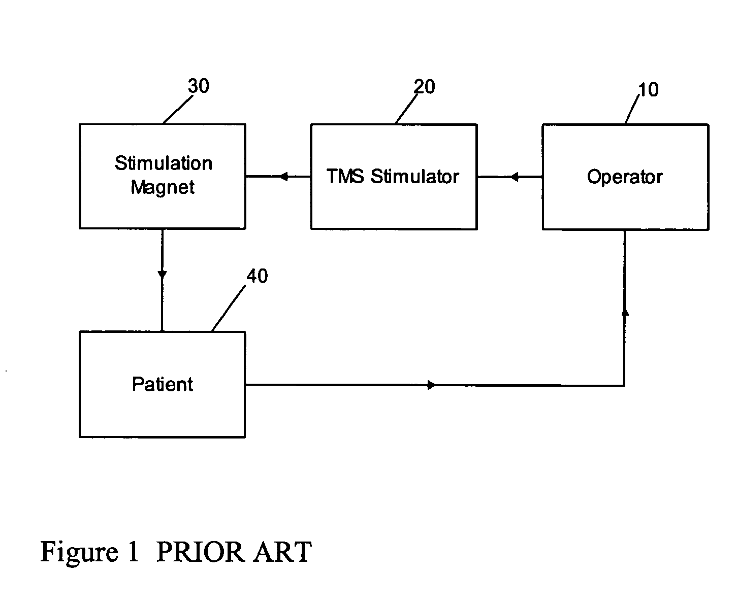
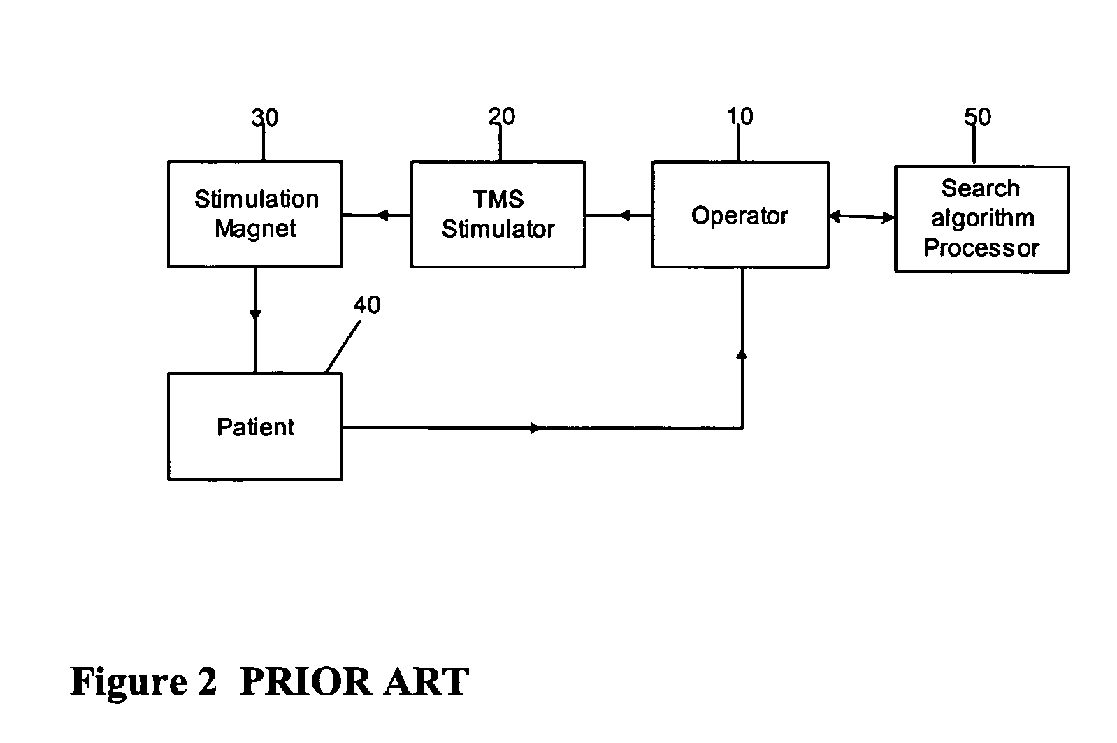
FIELD OF THE INVENTION [0001] The present invention relates to the field of electrical brain stimulation for the treatment of various illnesses. In particular, the invention relates to a method and apparatus for determining stimulation signal levels for applying electrical brain stimulation to a patient. BACKGROUND OF THE INVENTION [0002] Current methods of determining motor threshold (MT) position and stimulation levels for transcranial magnetic stimulation (TMS) studies rely on visual observation and interpretation of induced twitching of the thumb (i.e. abductor pollicis brevis) or by electromyography (EMG), which involves observation and interpretation of electrical response waveforms. In particular, a common method is to stimulate the motor cortex, observe thumb twitch or observe when the desired EMG signal exceeds a threshold value (i.e. motor evoked potential, MEP) as the stimulation level is manually adjusted. Both techniques are time consuming and highly dependent upon the ...

Claims


Application Information

Patent Timeline
IPC IPC(8): A61BA61N2/00A61N2/02
CPCA61N2/006A61B8/0808A61N2/02
Inventor RIEHL, MARK EDWARD
Owner NEURONETICS
Learn More