Spatial light modulator and display device

a technology of a display device and a light modulator, which is applied in the field of spatial light modulators and display devices, can solve the problems of further the contrast ratio of the displayed image, and achieve the effects of high contrast ratio, easy fabrication, and preventing the decrease of the contrast ratio

Inactive Publication Date: 2005-05-26
RICOH KK
View PDF55 Cites 58 Cited by
  • Summary
  • Abstract
  • Description
  • Claims
  • Application Information

AI Technical Summary

Benefits of technology

[0020] A first specific object of the present invention is to provide a spatial light modulation device that can be fabricated easily and is able to prevent decrease of a contrast ratio by suppressing a fringe effect, and a display device including the spatial light modulation device.
[0021] A second specific object of the present invention is to provide a display device with a high contrast ratio, which includes a pixel shift element and is able to display a number of pixels equaling an integral multiple of the number of pixels of a spatial light modulation device therein, and to reduce overlapping of adjacent pixels.

Problems solved by technology

Further, in a reflection spatial light modulator, the angle of the incident light entering the wave plate may differ from the angle of the returning light which leaves the wave plate, and this causes further decrease of the contrast ratio.
When such kind of illumination light is incident on the spatial light modulator, even in a dark state (no modulated light arrives at the projecting lens), leakage of the modulated light occurs, and the leaked modulated light arrives at the projecting lens and is projected onto the screen, causing decrease of the contrast ratio of the displayed image.
The above display devices, however, are not proposed to include a configuration with a λ / 4 wave plate being placed between the micro-lens array and the liquid crystal layer.

Method used


Image

  • Spatial light modulator and display device
  • Spatial light modulator and display device
  • Spatial light modulator and display device

Examples


first embodiment

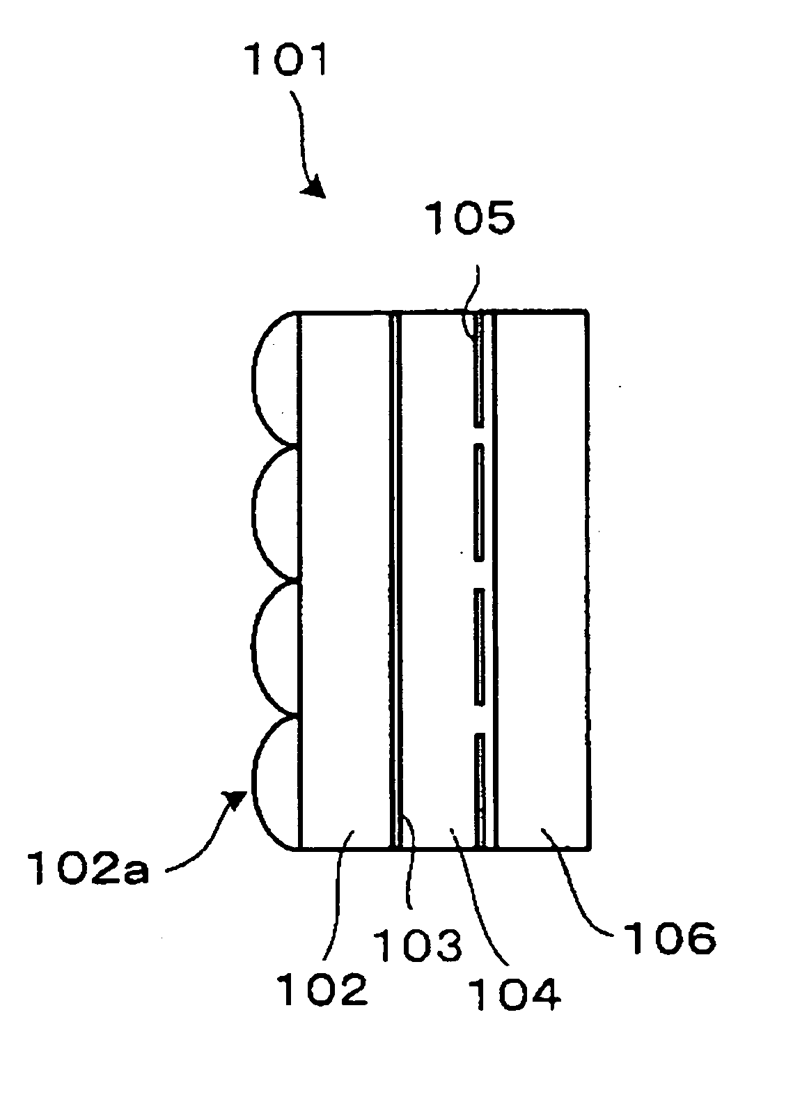
[0122]FIG. 1 is a schematic cross-sectional view of a principal portion of a spatial light modulator according to a first embodiment of the present invention.

[0123]FIG. 1 illustrates a spatial light modulator 101 which includes a lens array substrate 102 with a lens array 102a formed thereon, a wave plate 103, a liquid crystal layer 104, pixel reflecting electrodes 105 which are elements of a reflecting pixel array, and a silicon back substrate 106. Although not illustrated, a transparent electrode array and an alignment film are formed between the wave plate 103 and the liquid crystal layer 104. Further, an alignment film is also formed between the liquid crystal layer 104 and pixel reflecting electrodes 105. A spatial light modulator, such as the spatial light modulator 101, which employs liquid crystal displaying elements, is referred to as “liquid crystal light valve”.

[0124] Although not illustrated in FIG. 1, light from the left side in FIG. 1 is incident on the lens array 10...

second embodiment

[0180] In the spatial light modulator or display device of the first embodiment, a phase difference member is provided between a micro-lens array of the spatial light modulator and a liquid crystal layer, and the phase difference member is a structural birefringence film or an oblique evaporation film.

[0181] In the present embodiment, the phase difference member has a fixed liquid crystal alignment, even when the phase difference member is a structural birefringence film or an oblique evaporation film. In the related art, fabrication of such kinds of phase difference members is complicated, thus resulting in high cost. The present embodiment provides a spatial light modulator that can be easily fabricated.

[0182]FIG. 12 is a schematic cross-sectional view of a principal portion of a spatial light modulator according to the second embodiment of the present invention.

[0183] The spatial light modulator 201 illustrated in FIG. 12 includes a lens array substrate 202 with a micro-lens a...

example 4

[0288] The fourth example of the display device was another modification to the second example.

[0289] In this example, the phase difference member 203 of the spatial light modulator 201 was formed from a cured mixture of three polymerized liquid crystalline compounds (Tni=64.8° C.) represented by the following chemical formulae (1) to (3), and an optical polymerization initiator IRGACURE 184(0.5% weight percentage relative to the polymerized liquid crystalline compounds). This mixture was coated on the micro-lens substrate 202 processed by alignment treatment by using a polyimide rubbing film, and irradiated using ultraviolet rays at 50° C., and thus forming a phase difference member 203 having a thickness of 220 nm.

[0290] The thus formed phase difference member 203 generated a phase difference of 20 nm (Δn=0.09) relative to green light.

[0291] The interlayer 2034 was formed on the surface of the phase difference member 203 by sputtering SiO2 to a thickness of 200 nm. Next, the t...


PUM

PropertyMeasurementUnit
temperatureaaaaaaaaaa

Abstract

A spatial light modulator is disclosed that can be fabricated easily and is able to prevent degradation of a contrast ratio by suppressing a fringe effect. The spatial light modulator includes a light transmission substrate, a liquid crystal layer, a pixel array, and a phase difference generation unit provided between the light transmission substrate and the liquid crystal layer. A lens array is formed on the light transmission substrate, and the lens array has the same pitch as that of the pixel array.

Description

BACKGROUND OF THE INVENTION [0001] 1. Field of the Invention [0002] The present invention relates to a spatial light modulator, and a display device including the spatial light modulator. [0003] 2. Description of the Related Art [0004] In the related art, for example, Japanese Laid-Open Patent Application No. 11-258585 (referred to as “reference 1” hereinafter) discloses a display device including a reflection type spatial light modulator, such as a reflection type liquid crystal displaying element. This reflection spatial light modulator has a lens-array formed on a light transmission substrate. This lens-array prevents incidence of light on an area between two pixel electrodes where liquid crystal molecules are not sufficiently aligned, thereby obtaining an image of high brightness and high quality. [0005] Japanese Patent Gazette No. 3239969 (referred to as “reference 2” hereinafter) discloses a display device including a transmission type spatial light modulator, such as a transm...

Claims


Application Information

Patent Timeline
Patent Type & Authority Applications(United States)
IPC IPC(8): G02F1/13363G02B5/30G02F1/01G02F1/1333G02F1/1335G02F1/1337G02F1/139G02F1/141G03B21/00H04N5/74H04N9/31
CPCG02B5/3016G02F1/133365G02F1/133526G02F1/133553H04N9/3102G02F1/141G02F1/1418G02F2203/12H04N5/7441G02F1/133711
Inventor MIYAGAKI, KAZUYAFUJITA, KAZUHIROOSAKA, TAKANOBUTAKAURA, ATSUSHISUGIMOTO, HIROYUKITAKIGUCHI, YASUYUKI
Owner RICOH KK
Why Eureka
Try Eureka