Sensor system and methods for improved quantitation of environmental parameters

a sensor system and environmental parameter technology, applied in the field of optical analysis systems and methods, can solve the problems of not being able to easily emend quantitative analysis based on light absorbance, reflection, scattering, other optical phenomena, and the development of a sensor itself. existing optical analysis techniques have not been entirely satisfactory for the measurement of multiples

Inactive Publication Date: 2005-05-26
GENERAL ELECTRIC CO
View PDF17 Cites 29 Cited by
  • Summary
  • Abstract
  • Description
  • Claims
  • Application Information

AI Technical Summary

Benefits of technology

[0020] A system and method employing optical disk drives for quantitative analysis of chemical and biochemical parameters. Unlike other conventional optical drive-based systems, the detection method and associated detection system of the present disclosure utilizes a conventional dis

Problems solved by technology

The assay type used in this optical detection system is of a binary nature (see U.S. Pat. No. 6,342,349 column 15, lines 23-37) and is not easily emendable to quantitative analysis based on light absorbance, reflection, scatter, or other optical phenomena.
The limitations of such approach include development of a sensor itself, and its adaptation for computer control.
The interferences can arise from a variety of sources and can include chemical and environmental interferences.
Existing optical analysis techniques have not been entirely satisfactory for the measurem

Method used


Image

  • Sensor system and methods for improved quantitation of environmental parameters
  • Sensor system and methods for improved quantitation of environmental parameters
  • Sensor system and methods for improved quantitation of environmental parameters

Examples


Embodiment Construction

[0072] Exemplary embodiments of the present invention will be described below with reference to the accompanying drawings. In the following description, well-known functions or constructions are not described in detail to avoid obscuring the invention in unnecessary detail.

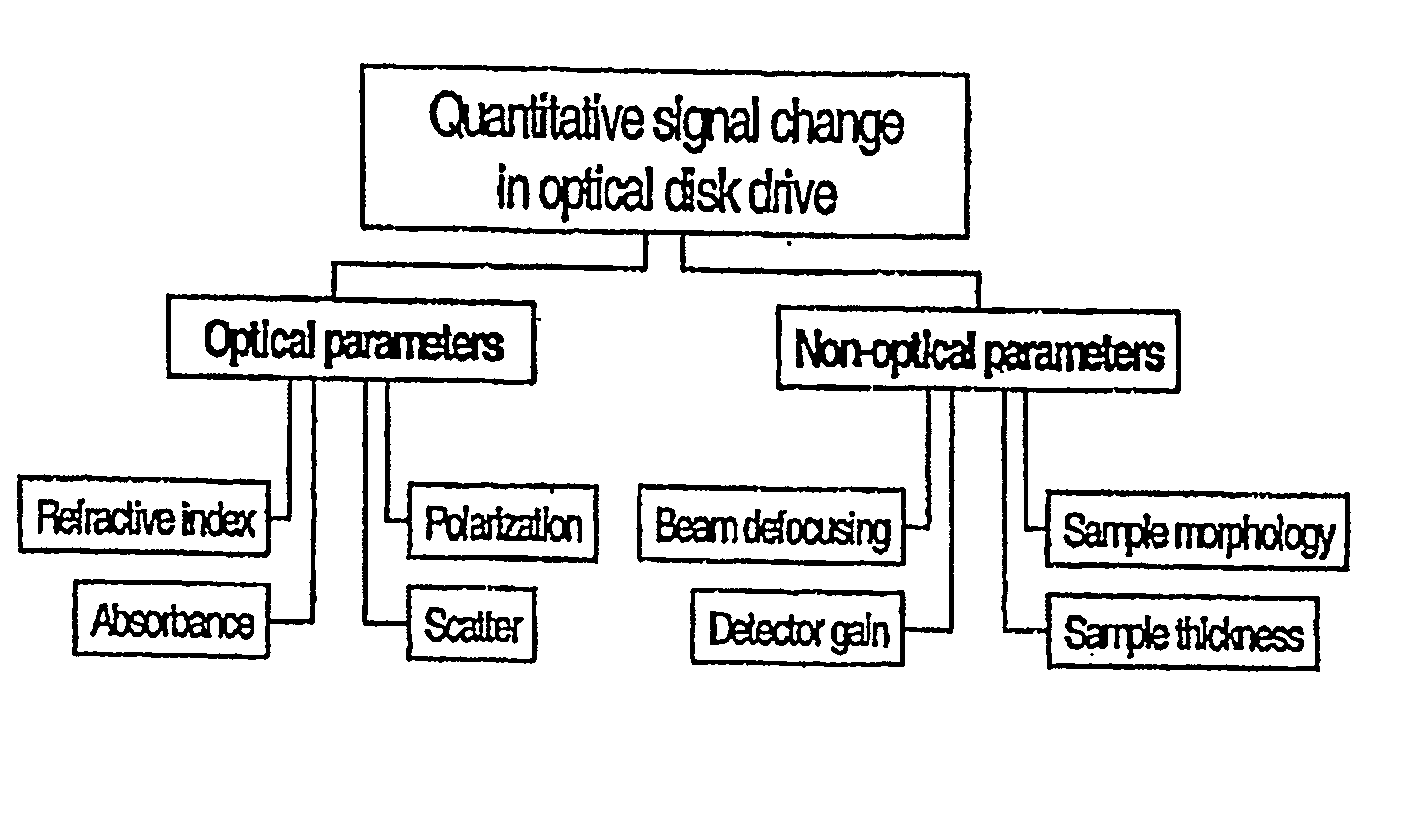
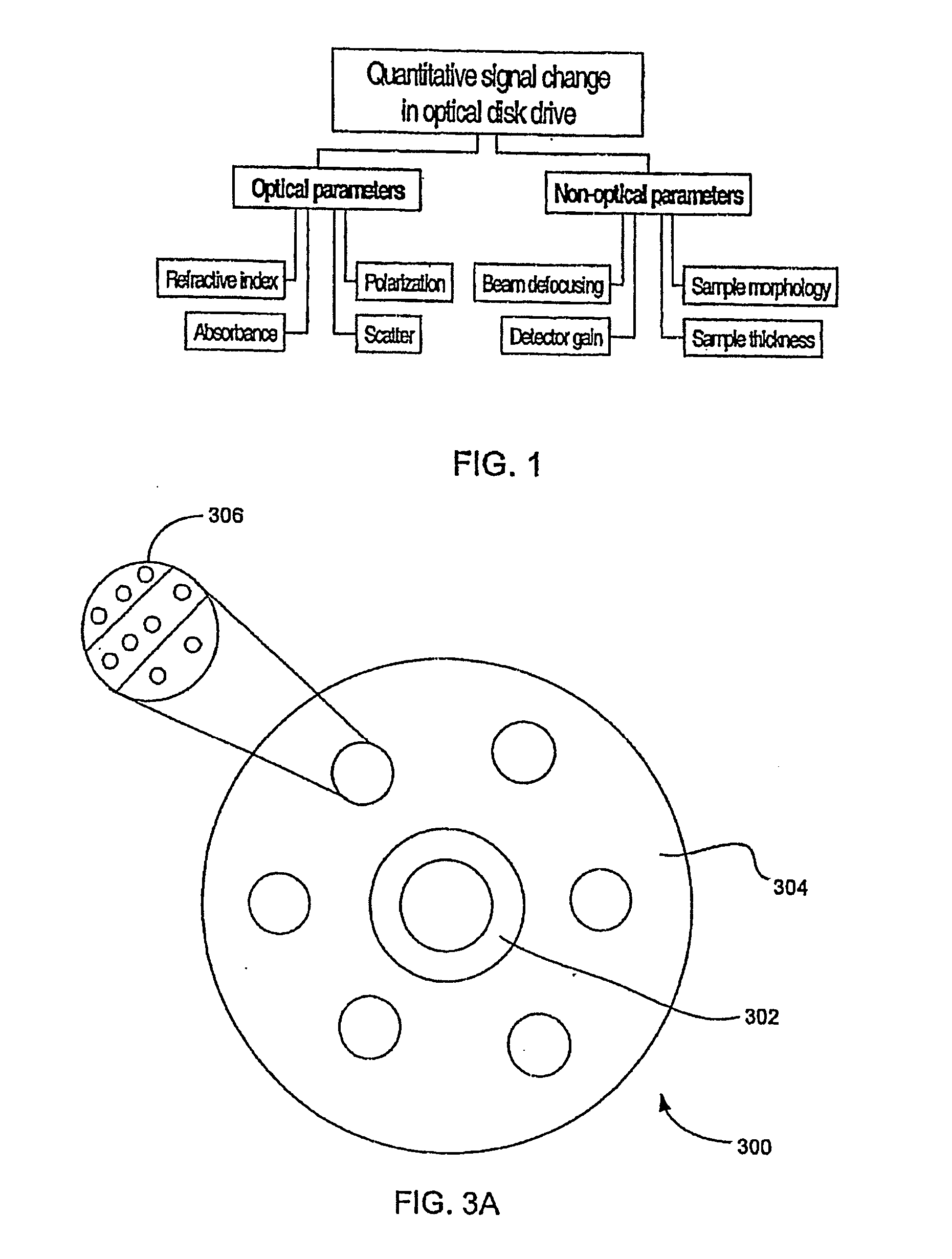
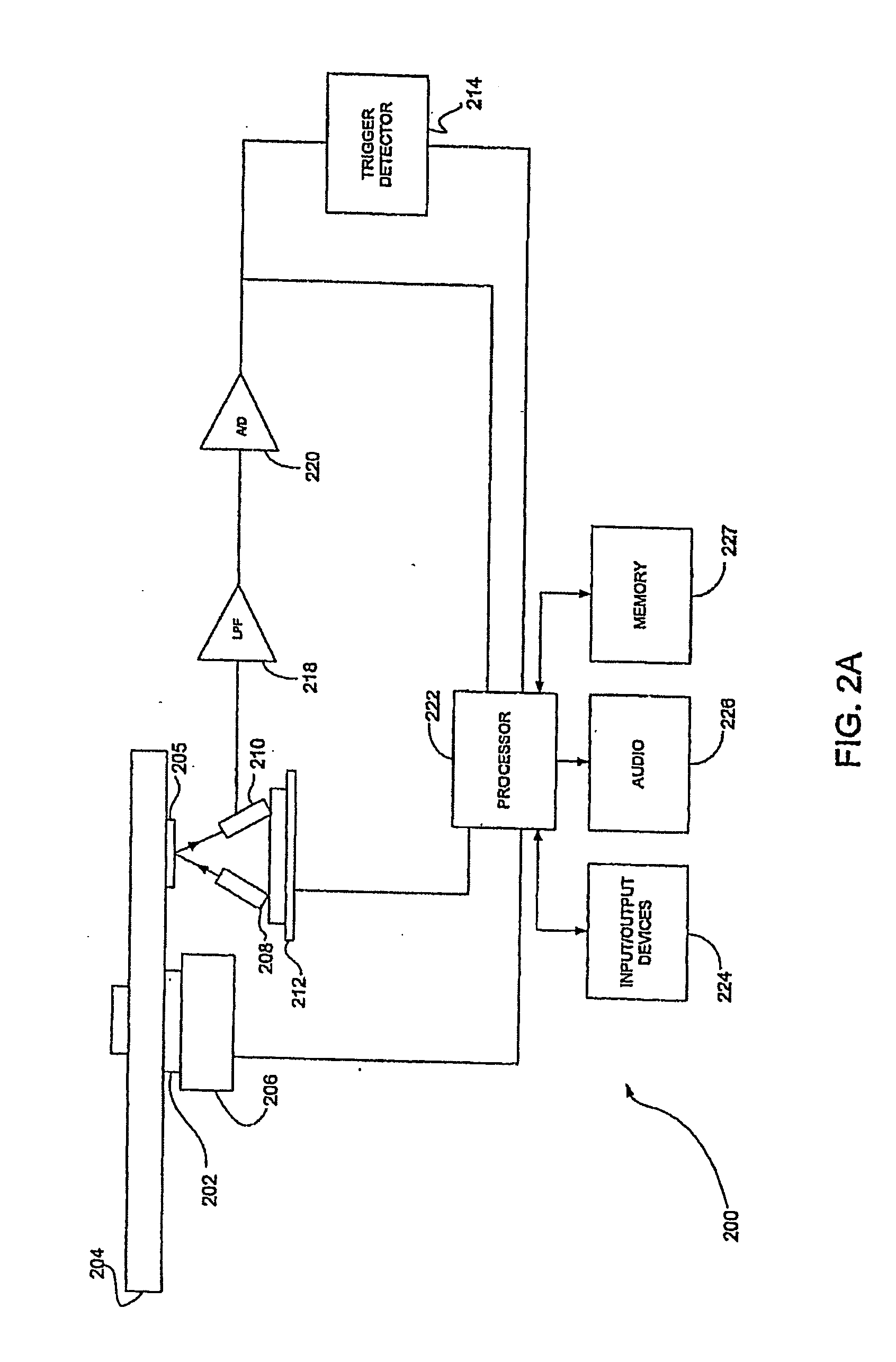
[0073] This invention uses an optical disc drive as a sensor readout device and provides quantitative information from an optical disc about variable optical properties of predetermined spatial locations on the disc. These predetermined spatial locations on the optical disc are defined as “sensor spots”. Depending on the application, the sensor spots are responsive to physical, chemical, biochemical, and other changes in the environment. The light that propagates through the sensor spot, reflects off the optical media's reflective layer, and propagates back through the sensor spot prior to detection and is modulated proportional to the change of various conditions, for example, a change proportional to the concen...


PUM


Abstract

A system and method employing optical disk drives for quantitative analysis of chemical and biochemical parameters, in which sensor materials disposed on an optical disk are responsive to physical, chemical, biochemical, and other parameters in the environment. The light interacts with the sensor materials when the light propagates through the sensor material, reflects off the optical media's reflective layer, and propagates back through the sensor region. The interacted light is captured by a photodetector, which outputs a response analog signal, for example, an analog voltage signal, which is indicative of a condition of the environment to which the sensor materials have been exposed. The system includes software algorithms which cause the laser source and optical detector to move to a specified location or logical block address of the disk, measure the optical signal during disk rotation, display a map of the sensor material response, and reduce the noise level in the measured signal.

Description

CROSS-REFERENCE TO RELATED APPLICATIONS [0001] This is a continuation-in-part application of U.S. application Ser. No. 10 / 915,890, filed Aug. 12, 2004, which is a continuation-in-part application of U.S. application Ser. No. 10 / 723,534, filed Nov. 24, 2003. The disclosures of both of these prior U.S. patent applications are hereby incorporated herein by reference.FIELD OF THE INVENTION [0002] The present invention relates generally to systems and methods for carrying out optical analysis of samples, and in particular relates to the measurement of changes in sensor materials for the quantitation of chemical and biological compounds in fluids and / or changes in physical parameters of the environment. BACKGROUND OF THE INVENTION [0003] Sensor methods and devices for quantification of volatile and nonvolatile compounds in fluids are known in the art. Typically, quantification of these parameters is performed using dedicated sensor systems that are specifically designed for this purpose. ...

Claims


Application Information

Patent Timeline
IPC IPC(8): B01L3/00G01N21/59G01N35/00
CPCB01J2219/00536B01J2219/00689B01J2219/00702B01L3/502715G01N35/00069B01L2300/024B01L2300/0806G01N21/5907B01L3/545
Inventor POTYRAILO, RADISLAV A.MORRIS, WILLIAM G.LEACH, ANDREW M.
Owner GENERAL ELECTRIC CO
Why Eureka
Try Eureka