Optical mask and MOPA laser apparatus including the same

Inactive Publication Date: 2005-05-26
HAMAMATSU PHOTONICS KK
View PDF7 Cites 58 Cited by
  • Summary
  • Abstract
  • Description
  • Claims
  • Application Information

AI Technical Summary

Benefits of technology

[0012] Incidentally, as another producing method of the serrated aperture mask, there is also a method that forms a chrome film, and then obtains a desired serrated shape at the fringe defining the aperture by etching. According to this etching, it is possible to approximate the serrated shape of the fringe defining the aperture of the serrated aperture mask to an ideal shape. But, a mask material for etching is necessary, and there are many steps since it is necessary to form an anti-reflection film so as to reduce the reflection from the glass substrate, resulting in a high manufacturing cost by etching as compared with the laser machining or electrical discharge machining.
[0013] The present invention is made to overcome the above-mentioned problems, and it is an object to provide a low-cost optical mask capable of reducing further the peak of beam intensity due to diffraction.
[0014] An optical mask according to the present invention includes: a first mask having a fringe, at least part of which is formed in a serrated shape; and a second mask having a fringe, at least part of which is formed in a serrated shape. Particularly, in the optical mask acc

Problems solved by technology

The inventors have studied above-mentioned prior art in

Method used


Image

  • Optical mask and MOPA laser apparatus including the same
  • Optical mask and MOPA laser apparatus including the same
  • Optical mask and MOPA laser apparatus including the same

Examples


Embodiment Construction

[0033] In the following, embodiments of an optical mask and an MOPA laser apparatus including the same according to the present invention will be explained in detail with reference to FIGS. 1 to 8. In the explanation of the drawings, constituents identical to each other will be referred to with numerals identical to each other without repeating their overlapping descriptions.

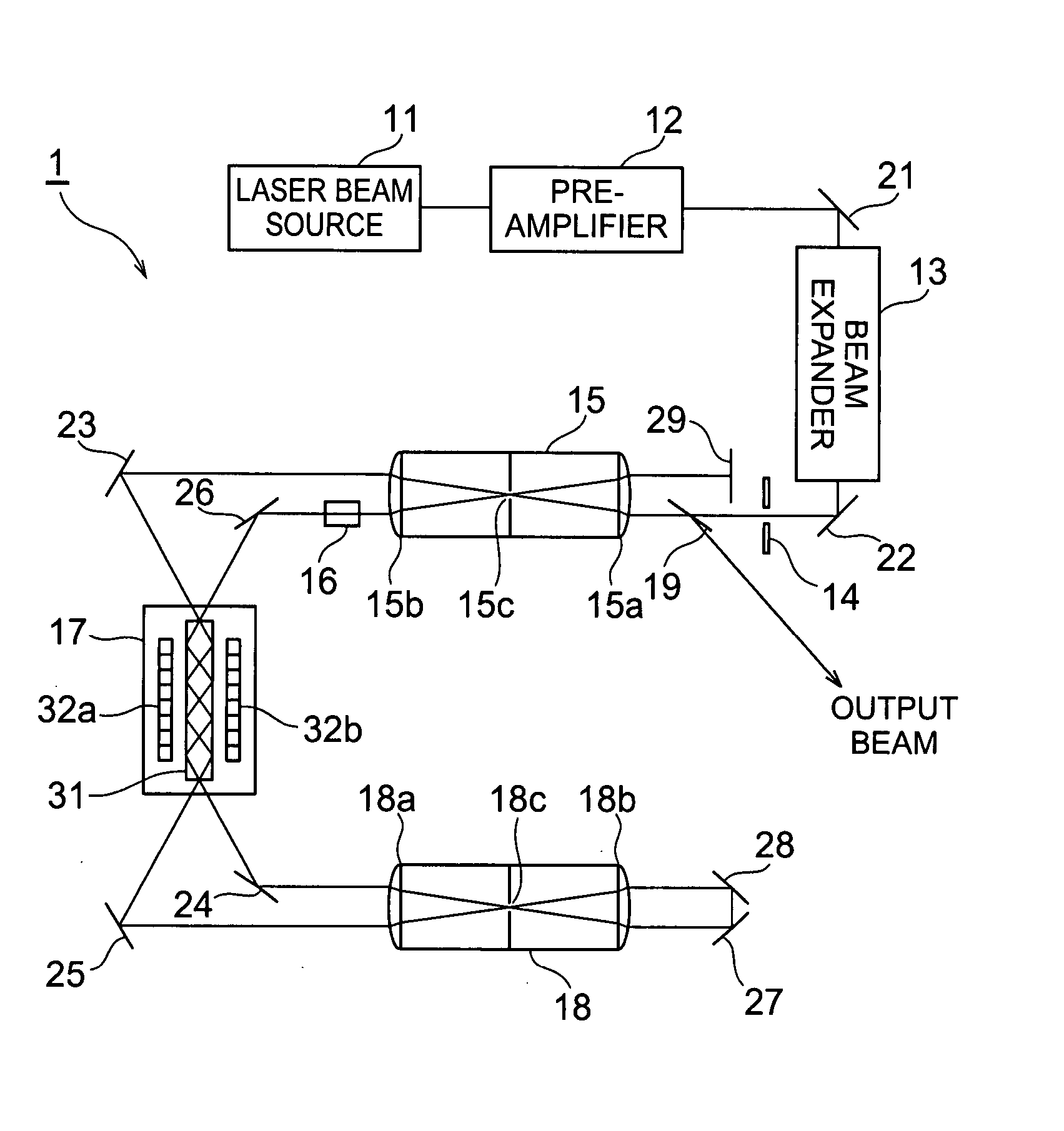
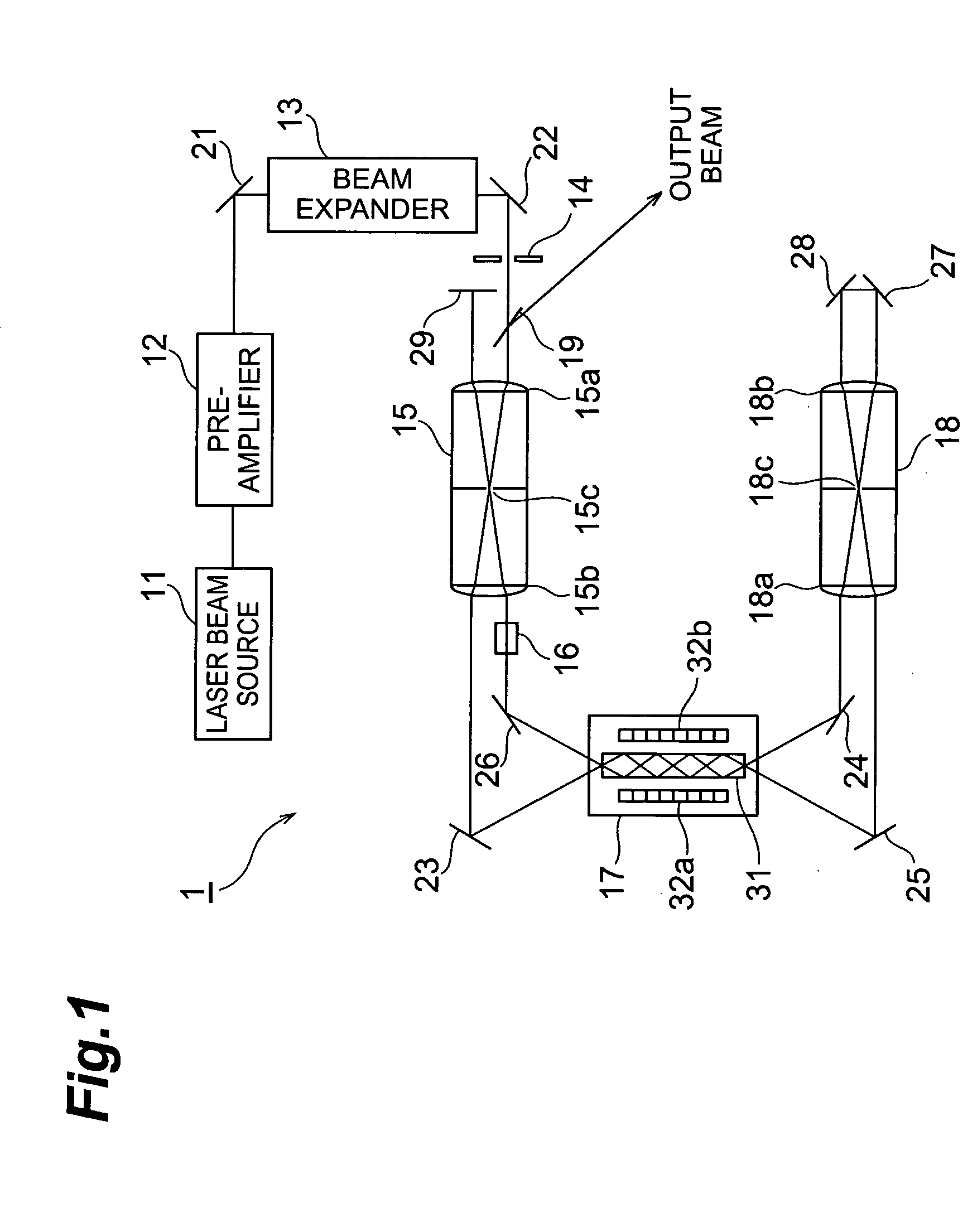
[0034] An MOPA laser apparatus 1 according to the present embodiment will be first described. FIG. 1 is a diagram showing a configuration of an embodiment of the MOPA laser apparatus according to the present invention. The MOPA laser apparatus 1 shown in this figure includes a laser beam source 11, a pre-amplifier 12, a beam expander 13, an optical mask 14, a spatial filter 15, a Faraday rotator 16, an laser amplifier 17, a spatial filter 18, and a polarizer 9.

[0035] The laser beam source 11 outputs a laser beam. The wavelength of the beam outputted from the laser beam source 11 is the one that may be amplifie...


PUM


Abstract

The present invention relates to an optical mask at low cost and so on having a structure capable of reducing further a peak of beam intensity caused by diffraction. The optical mask is constructed by overlapping a first mask and a second mask. The first mask and second mask each are a serrated aperture mask. The schematic shapes of the respective apertures of the first mask and second mask are almost rectangular and identical to each other. The fringe defining the aperture of the first mask is machined in a serrated shape, and the fringe defining the aperture of the second mask also is machined in a serrated shape. In the optical mask, the first mask and second mask are overlapped so that the serrations of the fringes defining the respective apertures of the first mask and second mask are located alternately.

Description

BACKGROUND OF THE INVENTION [0001] 1. Field of the Invention [0002] The present invention relates to an optical mask that shapes a spatial pattern of beam intensity, and an MOPA (Master Oscillator Power Amplifier) laser apparatus including that optical mask. [0003] 2. Related Background Art [0004] A hard aperture mask is known as an optical mask that shapes a spatial pattern of beam intensity. In the drawings, the area (a) in FIG. 9 shows a whole view of the hard aperture mask, and the area (b) in FIG. 9 is an enlarged view of section A. The hard aperture mask 80 has an aperture 80a having the same figure (substantially rectangular in an example as depicted) as that of the spatial pattern. In this figure, a hatching area represents a beam shielding section. And, the hard aperture mask 80 transmits through only this aperture 80a, and shields unnecessary beam, thereby shaping the spatial distribution of the laser beam to the same shape as the aperture shape. However, since in such a h...

Claims


Application Information

Patent Timeline
IPC IPC(8): H01S3/10G02B27/09H01S3/00H01S3/05H01S3/06H01S3/08H01S3/094H01S3/16H01S3/17H01S3/23
CPCG02B27/0988H01S3/005H01S3/0606H01S3/08H01S2301/20H01S3/1611H01S3/17H01S3/2341H01S3/08072
Inventor MATSUMOTO, OSAMUKAWASHIMA, TOSHIYUKIKANABE, TADASHI
Owner HAMAMATSU PHOTONICS KK
Why Eureka
Try Eureka