RF ID tag reader utlizing a scanning antenna system and method

a scanning antenna and reader technology, applied in the field of positioning determination and tracking systems, can solve the problems of reducing the range over which readers may communicate with tags, consuming large amounts of available tags, and currently available tags are relatively expensive, so as to enhance the reception of rf signals, maximize the information extracted from rf signals, and enhance the effect of rf signals

Inactive Publication Date: 2005-05-26
NXP USA INC
View PDF41 Cites 78 Cited by
  • Summary
  • Abstract
  • Description
  • Claims
  • Application Information

AI Technical Summary

Benefits of technology

[0013] An embodiment of the present invention may also include at least one conducting curtain associated with the card reader, wherein the at least one conducting curtain may be capable of enhancing reception of the RF signals by reflecting RF signals in the area. An embodiment may also provide for at least one element and at least one phase shifter in the scanning antenna array be capable of being used as a multiple input and multiple output (MINO) system to maximize information extracted from the RF signals.
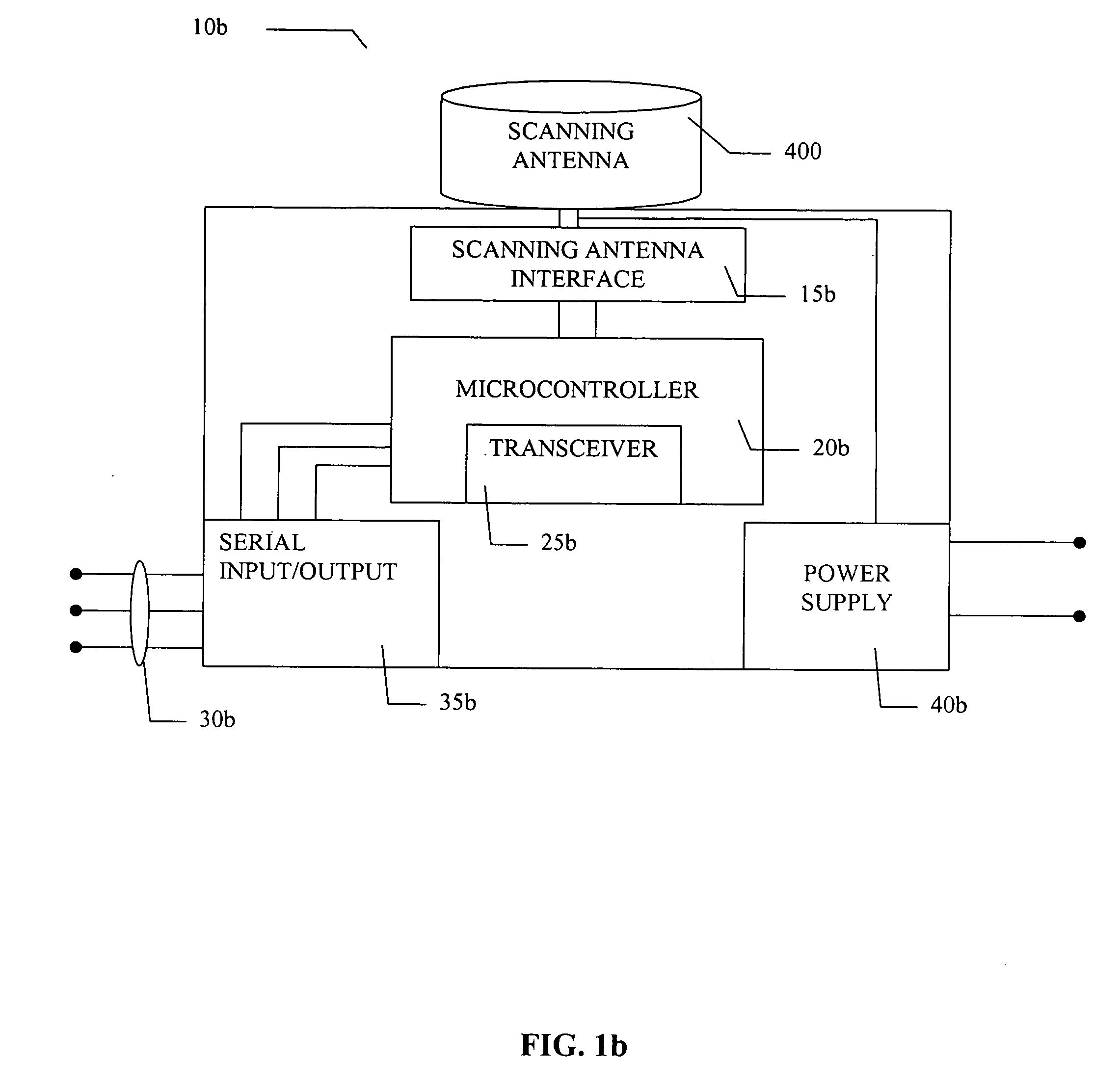
[0014] Another embodiment of the present invention provides for a method of tracking an object, person or thing, comprising associating an RF ID tag with the object, person or thing, and transmitting information to, and receiving information from, the RF ID tag by an RF ID tag reader with at least one antenna, the at least one antenna capable of creating a plurality of field focuses. Further, this method comprises using at least one antenna capable of creating at least one near field and at least one far field focus, wherein the antenna may do this by means of a scanning antenna (although the present invention is not limited in this respect). Also, the present method may further comprise, enhancing reception of the RF signals by reflecting RF signals with at least one conducting curtain. Also, the present method may further include using at least one element and at least one phase shifter in the scanning antenna array as a multiple input and multiple output (MIMO) system to maximize information extracted from said RF signals.

Problems solved by technology

For instance, currently available tags are relatively expensive.
Furthermore, currently available tags consume large amounts of power.
These inefficient power schemes also lead to reduced ranges over which readers may communicate with tags in a wireless fashion.
Still further, currently available readers and tags use inefficient interrogation protocols.
These inefficient protocols slow the rate at which a large number of tags may be interrogated.
However, if the tags are moved or are moving or do not possess their position information, their angular position cannot be determined.
Further, because the antennas are omni-directional and are constrained by FCC power limitations and other power constraints as mentioned above, the range is very severely limited.
Since omni-directional antennas always read all tags at all times, this limits the number of tags a reader can handle.
Also, when water or other types of liquids are present in the RF environment, the problem in communicating with a TAG becomes even more severe.
In fact, due to the attenuation produced by the liquid, the electromagnetic energy coming out of conventional antennas may not reach the tag with sufficient level, and therefore the tag will not be read.

Method used


Image

  • RF ID tag reader utlizing a scanning antenna system and method
  • RF ID tag reader utlizing a scanning antenna system and method
  • RF ID tag reader utlizing a scanning antenna system and method

Examples


first embodiment

[0042] The present invention serves as an internal or external antenna for a RF ID TAG reader application as well as a position determination and tracking system and method. The antenna interfaces with an RFID reader that can be used in a RF ID tag system for significant performance advantages. The antennas described herein can operate in any one, all or part of the following frequencies: the 2.4 GHz GHz Industrial, Scientific and Medical (ISM) band; the 5.1 to 5.8 GHz band; the 860-960 MHz band; or the 433 MHz band; although it is understood that they can operate in other bands as well. A software driver functions to control the antenna azimuth scan angle to maximize the received wireless signal from a tag associated with a reader. In a first embodiment, the key performance requirement to steer a beam with 6 dBi of gain throughout a 360° azimuth, or any segmentation of 360 degrees, scan is enabled

[0043] Existing RF ID TAG READERS currently use fixed antennas. Most often, omni-direc...

second embodiment

[0113] Referring to FIG. 17, there is a perspective view that illustrates the basic components of the array antenna 1102b. The array antenna 1102b has a similar structure and functionality to array antenna 1102a except that the antenna elements 1702 and 1704 are configured as dipole elements instead of a monopole elements as shown in FIG. 12. The array antenna 1102b includes a radiating antenna element 1702 capable of transmitting and receiving radio signals and one or more parasitic antenna elements 1704 that are incapable of transmitting or receiving radio signals. Each parasitic antenna element 1704 (six shown) is located a predetermined distance away from the radiating antenna element 1702. A voltage-tunable capacitor 1706 (six shown) is connected to each parasitic element 1704. A controller 1708 is used to apply a predetermined DC voltage to each one of the voltage-tunable capacitors 1706 in order to change the capacitance of each voltage-tunable capacitor 1706 and thus enable ...

third embodiment

[0115] Referring to FIG. 18, there is a perspective view that illustrates the basic components of the array antenna 1102c. The array antenna 1102c includes a radiating antenna element 1002 capable of transmitting and receiving dual band radio signals. The array antenna 1102c also includes one or more low frequency parasitic antenna elements 1804a (six shown) and one or more high frequency parasitic antenna elements 1804b (six shown). The parasitic antenna elements 1804a and 1804b are incapable of transmitting or receiving radio signals. Each of the parasitic antenna elements 1804a and 1804b are locate a predetermined distance away from the radiating antenna element 1802. As shown, the low frequency parasitic antenna elements 1804a are located on a circumference of a “large” circle around both the radiating antenna element 1802 and the high frequency parasitic antenna elements 1804b. And, the high frequency parasitic antenna elements 1804b are located on a circumference of a “small” ...


PUM


Abstract

An RF ID card reader, comprising, RF ID circuitry to generate an RF ID signal, a transceiver in communication with the RF ID circuitry, and an antenna associated with the transceiver for scanning an area for at least one tag and establishing communication with the at least one tag, the antenna capable of creating a plurality of field focuses. Further, the RF ID card reader of the present invention may provide that the plurality of field focuses may be a near field focus and a far field focuse. Also, the field focuses may be created by a scanning antenna array. An embodiment of the present invention may also include at least one conducting curtain associated with the card reader, wherein the at least one conducting curtain may be capable of enhancing reception of the RF signals by reflecting RF signals in the area. An embodiment may also provide for at least one element and at least one phase shifter in the scanning antenna array be capable of being used as a multiple input and multiple output (MIMO) system to maximize information extracted from the RF signals.

Description

CROSS-REFERENCE TO RELATED APPLICATION [0001] This application is a continuation in part of patent application Ser. No. 10 / 716,147, entitled, “RF ID TAG READER UTLIZING A SCANNING ANTENNA SYSTEM AND METHOD”“filed Nov. 18, 2003, by Jaynesh Patel et al, which was a continuation in part of patent application Ser. No. 10 / 388,788, entitled, “WIRELESS LOCAL AREA NETWORK AND ANTENNA USED THEREIN”“filed Mar. 14, 2003, by Hersey et al., which claimed the benefit of priority under 35 U.S.C Section 119 from U.S. Provisional Application Ser. No. 60 / 365,383, filed Mar. 18, 2002. BACKGROUND OF THE INVENTION [0002] 1. Field of the Invention [0003] This invention relates generally to position determination and tracking systems. More specifically, this invention relates to radio frequency identification (RFID) tag systems, methods and readers. Still more specifically, the present invention relates to RFID tags and tag readers that may utilize a scanning antenna or an electronically steerable passive...

Claims


Application Information

Patent Timeline
Patent Type & Authority Applications(United States)
IPC IPC(8): G06K7/08G06K7/10H01Q1/42H01Q3/36H01Q9/04H01Q21/20H01Q25/00
CPCG01S5/04G01S5/12G01S13/878G06K7/10079G06K7/10336H01Q25/00H01Q1/42H01Q3/36H01Q9/0407H01Q21/205G06K7/10346
Inventor MENDOLIA, GREGGUPTA, OMDU TOIT, CORNELIS FREDERIK
Owner NXP USA INC
Why Eureka
Try Eureka