High temperature strain gages

a strain gage and high temperature technology, applied in the direction of instruments, electrical/magnetic measuring arrangements, structural/machine measurement, etc., can solve the problems of limited scope of strain gage, limited use of strain gage alone, and limited tcrs

Inactive Publication Date: 2005-06-02
BOARD OF GOVERNORS FOR HIGHER EDUCATION STATE OF RHODE ISLAND & PROVIDENCE PLANTATIONS
View PDF1 Cites 21 Cited by
  • Summary
  • Abstract
  • Description
  • Claims
  • Application Information

AI Technical Summary

Problems solved by technology

Conventional strain gages are typically applied to both stationary and rotating components for this purpose but are usually limited in scope due to their intrusive nature, severe temperature limitations and difficulties in bonding.
When used alone is usually limited by relatively high TCRs as is the case for many intrinsic semiconductors.

Method used


Image

  • High temperature strain gages
  • High temperature strain gages
  • High temperature strain gages

Examples


Embodiment Construction

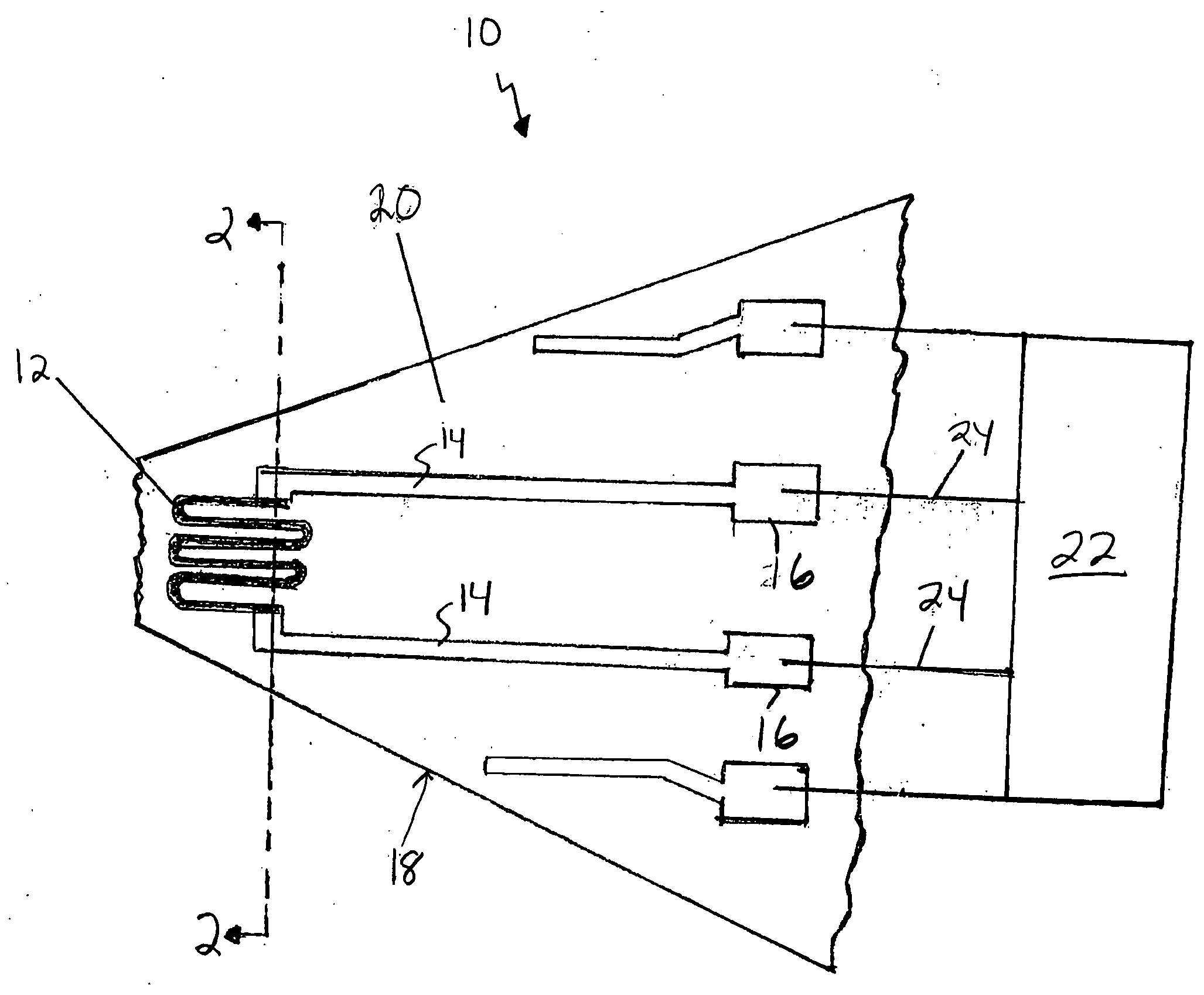
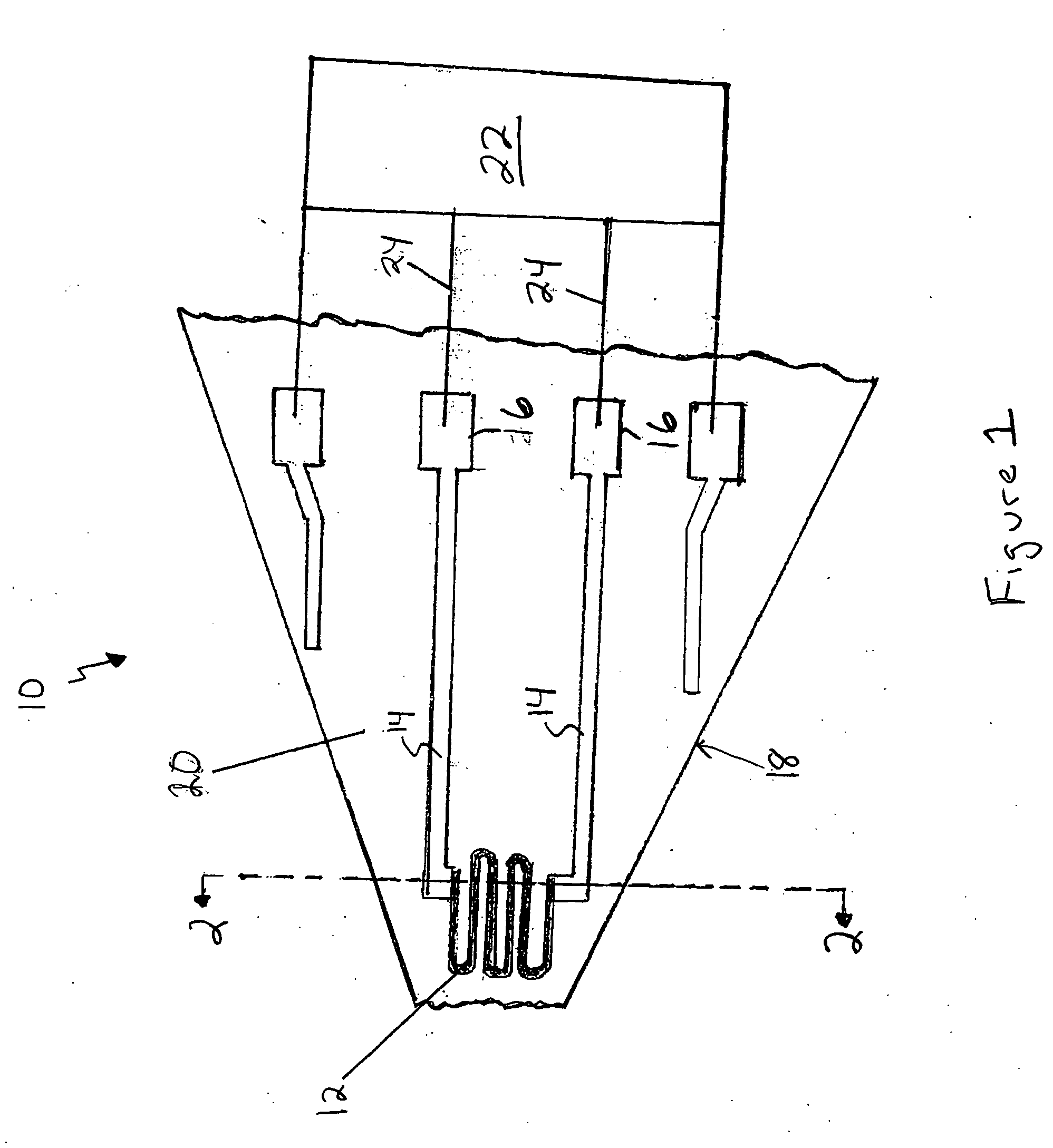
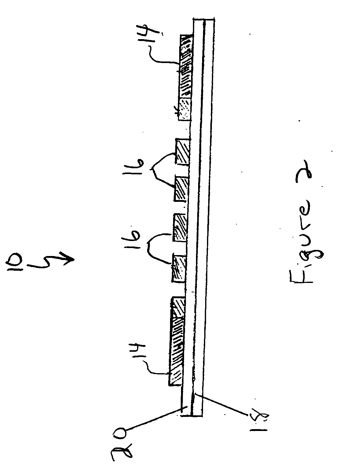
[0027] ITO strain gages with controlled nanoporosity were prepared by subjecting relatively thick ITO films to a post deposition anneal at 800° C. in nitrogen and exposing the same to high temperature, or by reactive sputtering in various nitrogen / oxygen / argon partial pressures and exposing to high temperature. SEM indicated that although the microstructures of the nitrogen-sputtered films were similar in appearance to those produced by a post deposition anneal in nitrogen, the average pore size and particle size were an order of magnitude smaller for those sensors prepared by sputtering in nitrogen overpressures. It appears that nitrogen was metastably retained in the individual ITO grains during sputtering and diffused out of the bulk grains at elevated temperature, eventually becoming trapped at grain boundaries and triple junctions. Under these conditions, sintering and densification of the ITO particles containing these nitrogen rich grain boundaries was retarded and a contiguo...


PUM

PropertyMeasurementUnit
temperatureaaaaaaaaaa

Abstract

A ceramic strain gage based on reactively sputtered indium-tin-oxide (ITO) thin films is used to monitor the structural integrity of components employed in aerospace propulsion systems operating at temperatures in excess of 1500° C. A scanning electron microscopy (SEM) of the thick ITO sensors reveals a partially sintered microstructure comprising a contiguous network of submicron ITO particles with well defined necks and isolated nanoporosity. Densification of the ITO particles was retarded during high temperature exposure with nitrogen thus stabilizing the nanoporosity. ITO strain sensors were prepared by reactive sputtering in various nitrogen / oxygen / argon partial pressures to incorporate more nitrogen into the films. Under these conditions, sintering and densification of the ITO particles containing these nitrogen rich grain boundaries was retarded and a contiguous network of nano-sized ITO particles was established.

Description

BACKGROUND OF THE INVENTION [0001] 1. Field of the Invention [0002] This invention relates generally to a high temperature ceramic strain gage. The gage is produced from indium-tin-oxide and can function at temperatures in excess of 1500° C. [0003] 2. Description of the Prior Art [0004] The accurate measurement of both static and dynamic strain, at elevated temperatures is frequently required to determine the instabilities and life-times of various structural systems, and in particular, advanced aerospace propulsion systems. Conventional strain gages are typically applied to both stationary and rotating components for this purpose but are usually limited in scope due to their intrusive nature, severe temperature limitations and difficulties in bonding. [0005] Thin film strain sensors are particularly attractive in the gas turbine engine environment since they do not adversely effect the gas flow over the surface of a component and do not require adhesive or cements for bonding purpo...

Claims


Application Information

Patent Timeline
Patent Type & Authority Applications(United States)
IPC IPC(8): G01L1/00
CPCG01L1/2287G01M5/0083
Inventor GREGORY, OTTO J.YOU, TAO
Owner BOARD OF GOVERNORS FOR HIGHER EDUCATION STATE OF RHODE ISLAND & PROVIDENCE PLANTATIONS
Why Eureka
Try Eureka