Flat fluorescent lamp and backlight unit using the same

a fluorescent lamp and fluorescent lamp technology, applied in the field of flat fluorescent lamps and backlight units using the same, can solve the problems of inability to display images, increased power consumption, disadvantageous use of fluorescent materials by above fluorescent lamps, etc., and achieve the effects of improving luminance, low voltage, and widening the electrode width

Inactive Publication Date: 2005-06-02
LS TECH
View PDF5 Cites 30 Cited by
  • Summary
  • Abstract
  • Description
  • Claims
  • Application Information

AI Technical Summary

Benefits of technology

[0025] The backlight unit using the flat fluorescent lamp of the present invention is advantageous in terms of improved luminance by the formation of the reflective layer, and low voltage required to initiate a discharge by widening widths of the electrodes due to the formation of apertures of the electrodes. In addition, a plasma discharge region is adjusted, thereby increasing uniform luminance characteristics. Also, durability of the flat fluorescent lamp can be supplemented upon combination of the base member and the flat fluorescent lamp.

Problems solved by technology

However, the liquid crystal display per se has no a light-emitting structure, and cannot display an image unless light is externally irradiated.
Hence, with the intention of obtaining large quantities of light, the discharge channel of the above lamp 10 should be enlarged and an operation power should increase, resulting in increased power consumption.
Consequently, the above fluorescent lamp is disadvantageous in terms of using an expensive fluorescent material, instead of a mass-produced fluorescent material for ultraviolet rays of 254 μm.
However, as the discharge channel becomes longer, a voltage required to initiate the discharge increases.
In cases of increasing the discharge voltage, the lamp may suffer from unstability, current leakage and electronic wave problems.
Hence, it is impossible to realize a circuit required for such a discharge voltage.
Although such a flat fluorescent lamp is difficult to fabricate because of molding the heated glass plate to define the discharge channels, it has no problems related to the application of the high voltage to the electrodes.
However, crosstalk between the discharge channels may occur, due to a strong discharge in a specific discharge channel among the discharge channels or severely shaking discharge plasma.
However, such a flat fluorescent lamp suffers from drawbacks, such as non-uniform luminance, due to weak light emission at an edge of the discharge channel, requirement of a high discharge voltage, and easy deterioration of the electrodes.

Method used


Image

  • Flat fluorescent lamp and backlight unit using the same
  • Flat fluorescent lamp and backlight unit using the same
  • Flat fluorescent lamp and backlight unit using the same

Examples


first embodiment

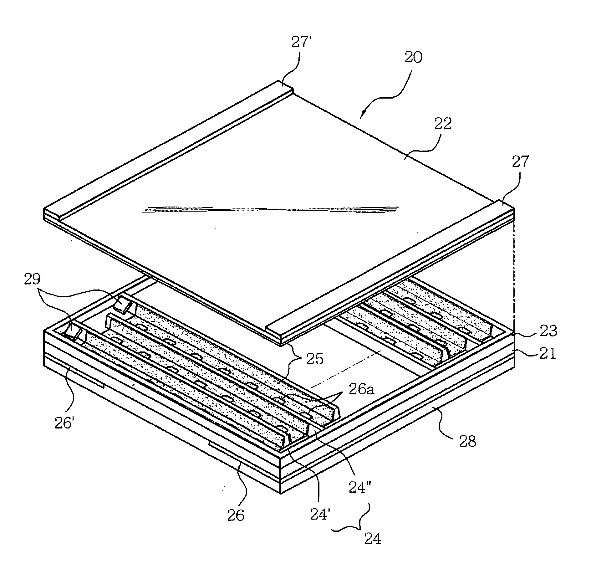
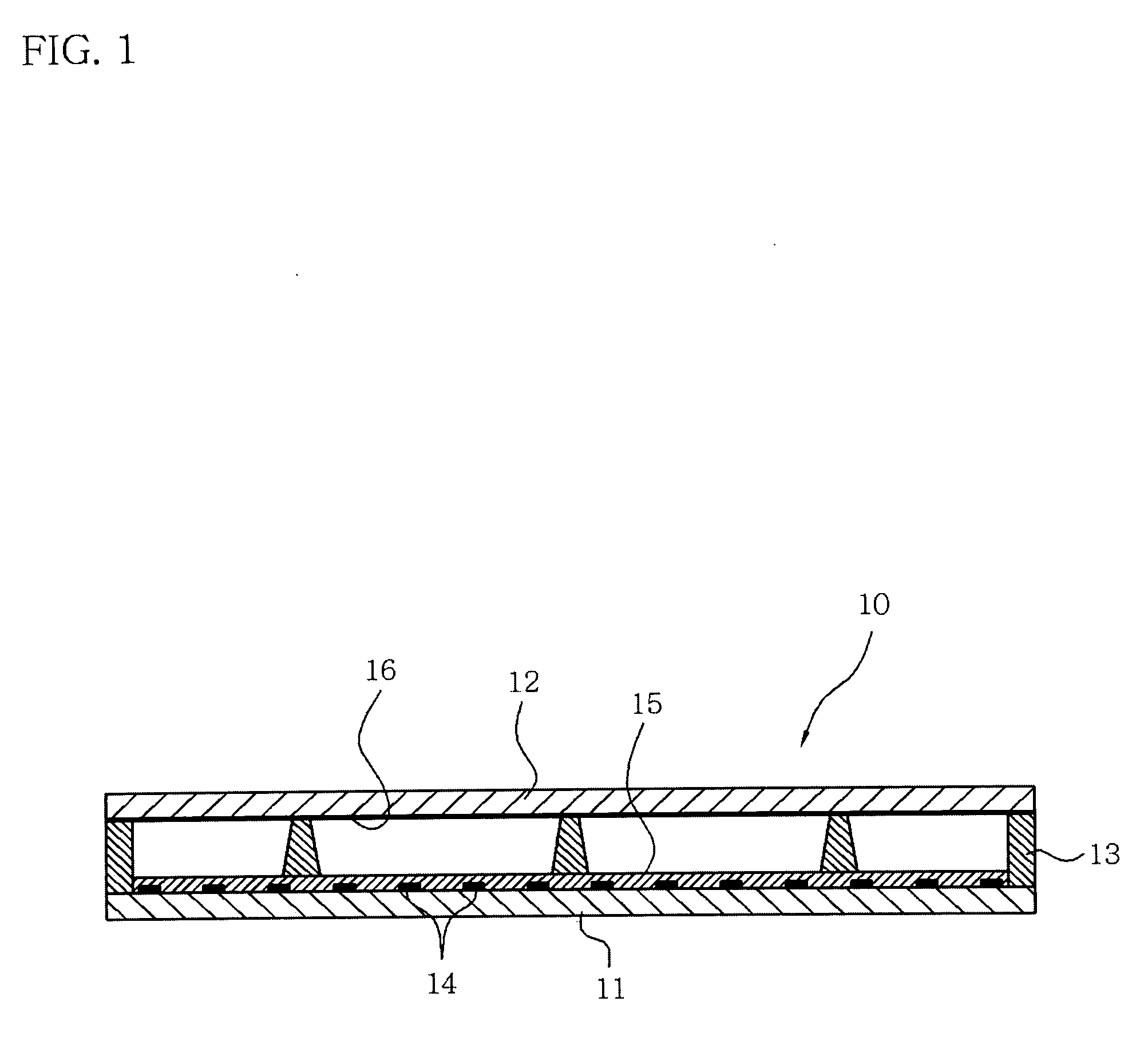
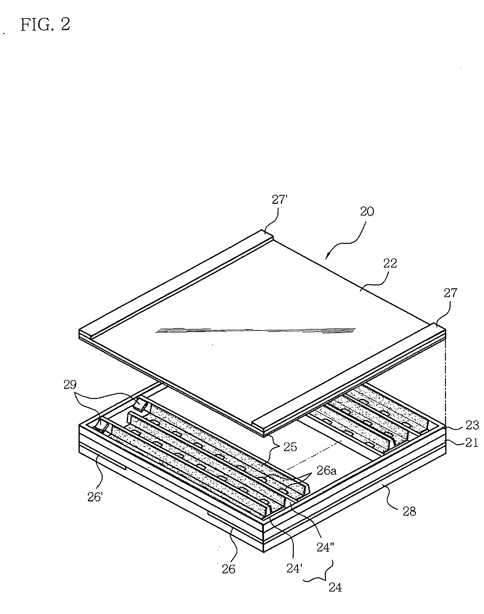
[0036]FIG. 2 is an exploded perspective view of a flat fluorescent lamp, according to the present invention, and FIG. 3 is a cross-sectional view taken along the line A-A of FIG. 2.

[0037] As shown in FIGS. 2 and 3, a flat fluorescent lamp 20 includes a back substrate 21, a front substrate 22, partitions 24, a fluorescent material layer 25, electrodes 26, 26′, 27 and 27′, and a reflective layer 28.

[0038] Specifically, the flat fluorescent lamp 20 has the back substrate 21, and the front substrate 22 placed onto the back substrate 21 through a sealing member 23. Also, a plurality of the partitions 24, which define a discharge channel of a zigzag shape between the back substrate 21 and the front substrate 22, are in close contact with the front substrate 22 and are alternately disposed to be spaced from each other by a predetermined interval. Further, two pairs of the electrodes 26, 26′ and 27, 27′ are disposed to both ends of the back substrate 21 and both ends of the front substrate...

second embodiment

[0057] Turning now to FIG. 7, there is shown an exploded perspective view of a flat fluorescent lamp, according to the present invention.

[0058] As shown in FIG. 7, the flat fluorescent lamp 20 includes a back substrate 21, a front substrate 22, partitions 24, a fluorescent material layer 25, and electrodes 26, 26′, 27 and 27′. The flat fluorescent lamp 20 according to the second embodiment of the present invention has the same structure to that according to the first embodiment of the present invention, with the exception of the reflective layer 28 of the first embodiment.

[0059] That is, as for the flat fluorescent lamp 20 according to the second embodiment, the front substrate 22 is mounted to the back substrate 21 through a sealing member 23. A plurality of partitions 24, defining a discharge channel of a zigzag shape between the back substrate 21 and the front substrate 22, are in close contact with the front substrate 22 and are alternately disposed to be spaced from each other...


PUM

PropertyMeasurementUnit
thicknessaaaaaaaaaa
widthsaaaaaaaaaa
transparentaaaaaaaaaa

Abstract

Disclosed is a flat fluorescent lamp, including a back substrate, a front substrate made of a transparent material and mounted on the back substrate through a sealing member disposed therebetween, a plurality of partitions disposed between the back and front substrates to define a discharge channel therebetween, a fluorescent material layer coated along a surface of the discharge channel defined by the partitions, a plurality of electrodes disposed to both the back substrate and the front substrate to cause a dielectric barrier discharge, and a reflective layer to cover the entire back substrate and upper portions of the electrodes disposed to the back substrate. In addition, a backlight unit is provided, including the above flat fluorescent lamp, a light diffusion part spaced from a top of the front substrate of the flat fluorescent lamp to diffuse light irradiated from the flat fluorescent lamp, an insulating layer disposed under the reflective layer of the flat fluorescent lamp through a first adhesive layer, and a base member disposed under the insulating layer through a second adhesive layer. Such a backlight unit is advantageous in improvement of uniform characteristics of luminance and supplement of durability of the lamp upon combination of the lamp and the base member.

Description

BACKGROUND OF THE INVENTION [0001] 1. Field of the Invention [0002] The present invention relates, in general, to flat fluorescent lamps and backlight units using the same, and more specifically, to a flat fluorescent lamp having an electrode structure to cause a dielectric barrier discharge, and a backlight unit using the same. [0003] 2. Description of the Related Art [0004] In general, a flat display device is classified into a light-emitting type and a light-receiving type, in which the light-emitting type display device includes a cathode ray tube, an electron light-emitting device, a plasma display panel, etc., and the light-receiving type display device is exemplified by a liquid crystal display. [0005] However, the liquid crystal display per se has no a light-emitting structure, and cannot display an image unless light is externally irradiated. Thus, an additional light source, for example, a backlight unit, is mounted to display the image. [0006] Such a backlight unit acts t...

Claims


Application Information

Patent Timeline
Patent Type & Authority Applications(United States)
IPC IPC(8): G02F1/13357H01J1/62H01J61/00H01J61/30H01J65/04
CPCH01J65/046H01J61/305
Inventor PARK, DEUK-ILRHEW, CHOONG-YOPSUR, OK-BIN
Owner LS TECH
Why Eureka
Try Eureka