[0012] Although the principle of measuring the
ground speed of a vehicle via a radar sensor is conventional, the
advantage of the present invention is that this
speed measurement does not require an additional radar sensor, but, rather, is achieved by only a minor modification of a radar sensor, present in the vehicle anyway and used as such for other purposes, for example an ACC system.
[0013] In one use of the radar sensor according to the present invention in an ACC system, the advantageous possibility is also provided for using the radar lobe directed onto the roadway surface for continuously checking the
vertical alignment of the radar sensor. A correct alignment of the radar sensor in the vertical direction is of greater importance in ACC systems because the desired localization depth of the sensor is not obtained unless radar lobes are aligned precisely at the height of the other vehicles, and thus approximately parallel to the roadway surface. Otherwise, there is a risk that the radar lobes either pass over vehicles at a distance when the alignment is too high, or strike the ground before reaching the vehicle at a distance when the alignment is too low. Since by using the lobe directed onto the roadway surface it is possible to measure not only the absolute speed of the vehicle but also the distance at which this radar lobe impinges on the roadway, the angular alignment of the sensor may be checked based on this distance and the known height of the radar sensor above the roadway surface.
[0014] It is also possible to improve the accuracy and reliability of an automatic
blindness recognition system of the sensor using the radar sensor according to the present invention. Although the radar
waves are able to penetrate rain and
fog better than the
human eye, the radar sensor may be blinded due to various causes. Possible reasons for such blinding, besides the sensor misalignment already mentioned, are errors or breakdowns of the sensor
electronics, and in particular, deposits of
snow,
slush, or ice on the radar antenna or on the lens which bundles the radar beams.
Blindness recognition systems for ACC radar sensors are described in German
Patent Application Nos. DE 196 44 164 and DE 199 45 268. In the system described in the latter application, the echoes from vehicles traveling ahead and other targets on the roadway or on the side of the roadway detected by the radar sensor are evaluated for this purpose. One
disadvantage of this system, however, is that blinding of the sensor is erroneously identified in a very low-reflecting environment, such as when driving on a seldom traveled road in barren areas, where there are also no reflecting targets on the roadside. In contrast, the present invention has the
advantage that the radar echo from the roadway surface is practically always present, and at a known intensity of the emitted
signal also has an intensity that is predictable within certain limits. If the intensity of the echo from the roadway surface takes on abnormally low values, this is a very meaningful indicator of blinding of the radar sensor. Because the channel scanning the roadway surface and the channels responding to other vehicles are integrated into the same radar sensor, an absence of the radar echo from the roadway indicates that in all probability the sensor as a whole has been blinded.
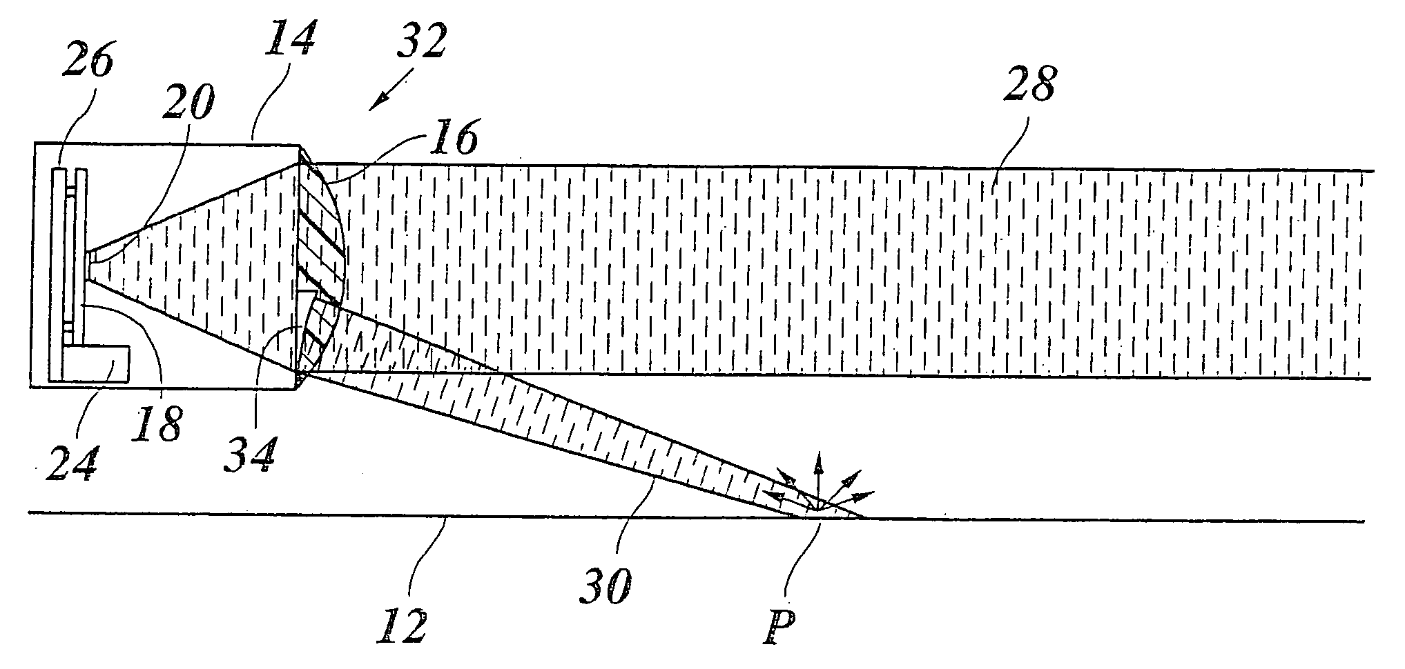
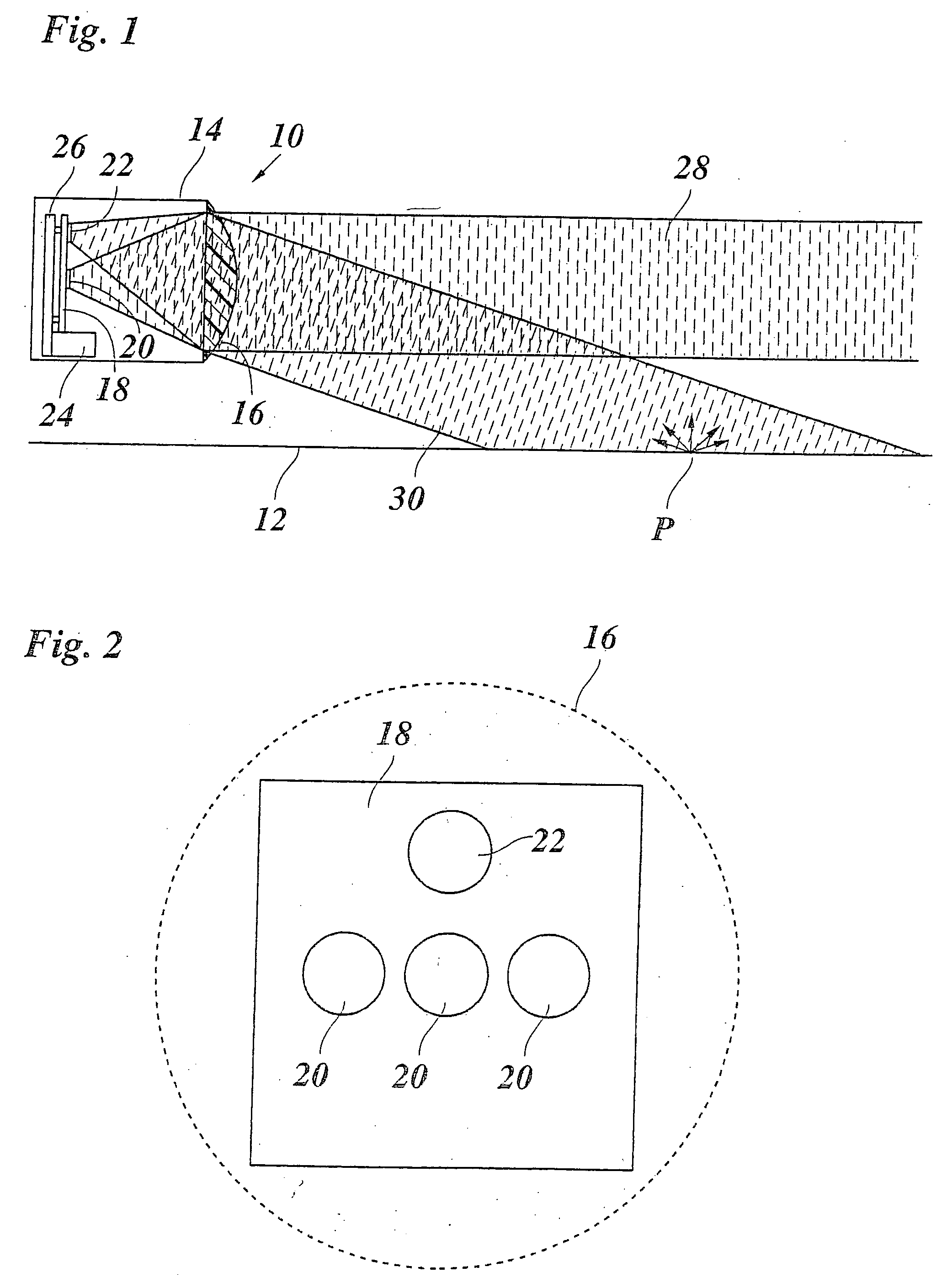
[0015] In one example embodiment, the lobe directed onto the roadway surface is generated by an additional radar source, a
patch antenna, for example, which is situated above the
optical axis of the sensor and whose beam is therefore deflected through the lens onto the roadway surface. In this case the echo from the roadway surface is also received mainly by the offset patch, thereby simplifying a targeted evaluation of this
signal.
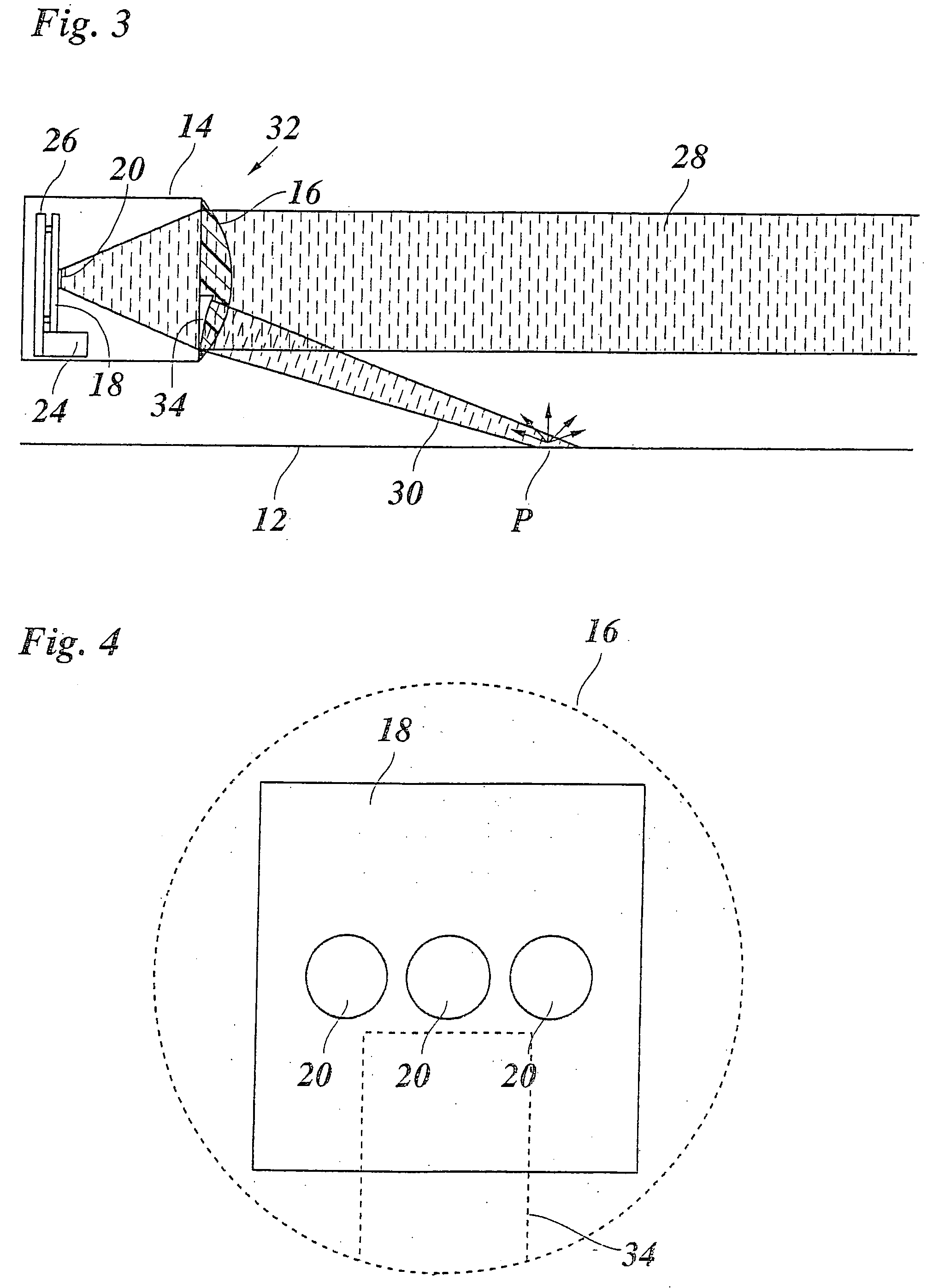
[0016] In another example embodiment, the
radar beam which is generated by one or more radar sources and directed parallel to the roadway surface is partially deflected onto the roadway surface with the aid of a condenser which acts as a
beam splitter. The condenser may be a specially designed lens which has two lens zones with different refractive properties, similar to bifocal eyeglasses. Of course, this may also be achieved by an appropriately designed reflector. In these cases, the radar echo from the roadway surface is evaluated via the channels which are also used for evaluating the signals from other radar targets.
[0017] The present invention is not limited to a specific design of the radar sensor or
transmitter /
receiver principle, but, rather, may be used for all common sensor types with appropriate modification of the electronic
evaluation system or
software.

