Method of manufacturing ink jet recording head, ink jet recording head, and ink jet cartridge

a technology of ink jet recording head and manufacturing method, which is applied in printing and other directions, can solve the problems of affecting the yield affecting the precision of manufactured head, and affecting the quality of high-precision head manufacturing, so as to prevent physical breakage of filter structure, facilitate manufacturing, and improve the effect of strength

Inactive Publication Date: 2005-06-02
CANON KK
View PDF13 Cites 15 Cited by
  • Summary
  • Abstract
  • Description
  • Claims
  • Application Information

AI Technical Summary

Benefits of technology

[0016] The above-described ink jet recording head can be easily manufactured by the above-described manufacturing method. As a further preferable aspect, the channel forming member may be constituted to form the organic film in a region of a part of the opening of the liquid supply port. Accordingly, for example, when a liquid flows into a liquid channel from the liquid supply port with great force, a filter structure can be prevented from being pushed and broken by the liquid. Therefore, strength against physical breakage of the filter structure can be enhanced.
[0017] Moreover, the filter structure has a plurality of filter holes. Assuming that a diameter of the discharge port or the liquid channel whose diameter is smaller is A, and a diameter of the filter hole is B, the filter may be constituted in such a manner that a relation of A≧B is established. When the diameter of the discharge port or the liquid channel has this relation with that of the filter hole, the foreign matters passed through the filter structure can be discharged to the outside through the discharge port, and therefore the discharge port and the liquid channel are not prevented from being clogged with the foreign matters.

Problems solved by technology

However, in the U.S. Pat. Nos. 6,264,309 and 6,543,884, there is a fear that the dust or foreign matters are mixed into the nozzles during lamination in the constitution in which the members for forming the discharge ports and channels are laminated with respect to the silicon substrate provided with the ink supply port.
Therefore, when the method described in the above-described document is to be applied to the method described in the U.S. Pat. No. 5,478,606, a soluble resin for forming the channels is immersed in an etching solution for forming the ink supply port, and there is a possibility that precision of the manufactured head, or yield of high-precision head manufacturing is adversely affected.
The film is exposed in various solutions in subsequently performed steps and corroded, or finely damaged during conveyance in a semiconductor manufacturing apparatus during a manufacturing process in some case.
Therefore, it has been very difficult to keep the filter by the insulating film without any defect until a final product is manufactured.

Method used


Image

  • Method of manufacturing ink jet recording head, ink jet recording head, and ink jet cartridge
  • Method of manufacturing ink jet recording head, ink jet recording head, and ink jet cartridge
  • Method of manufacturing ink jet recording head, ink jet recording head, and ink jet cartridge

Examples


first example

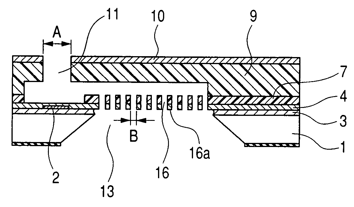
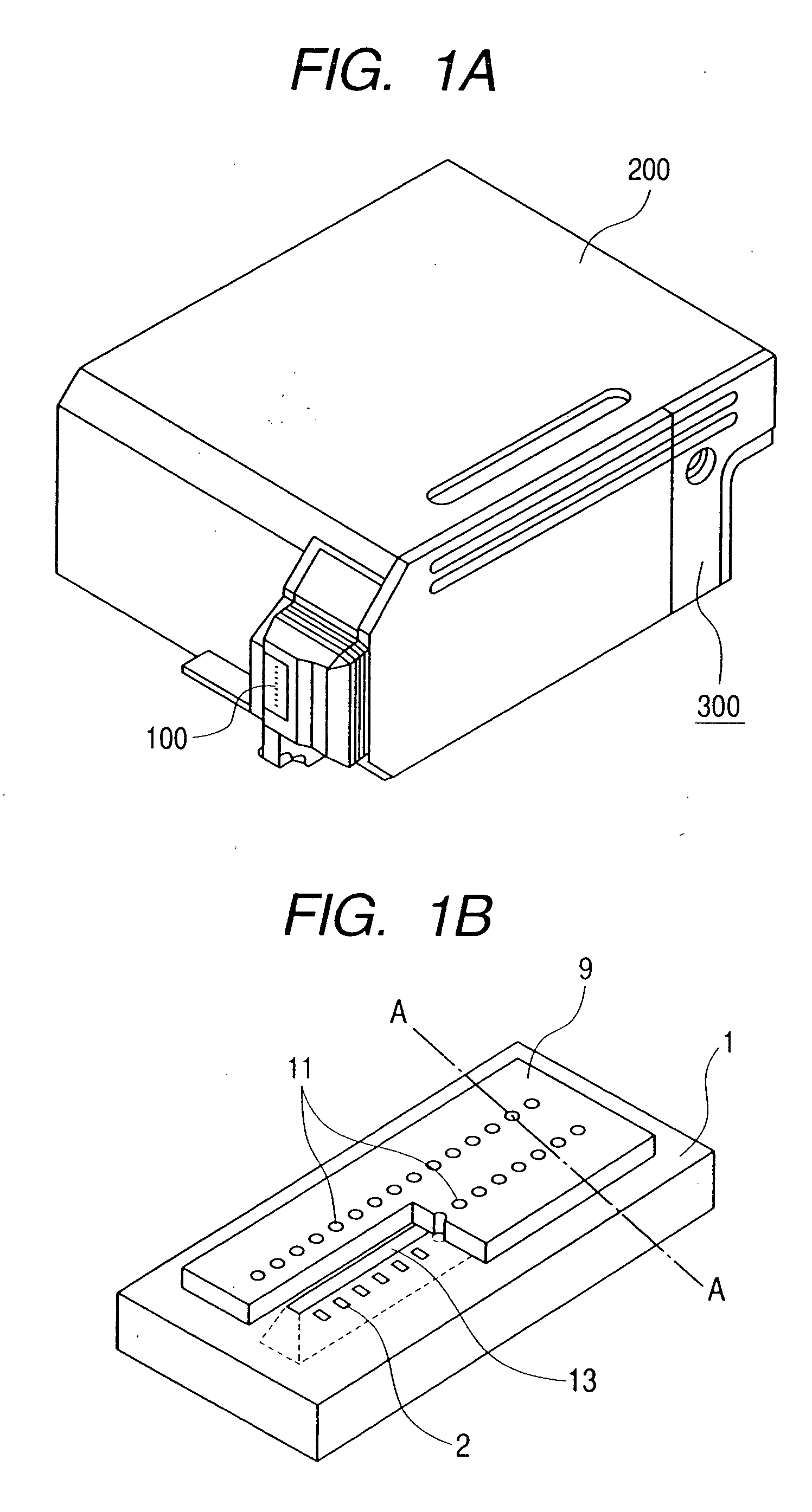
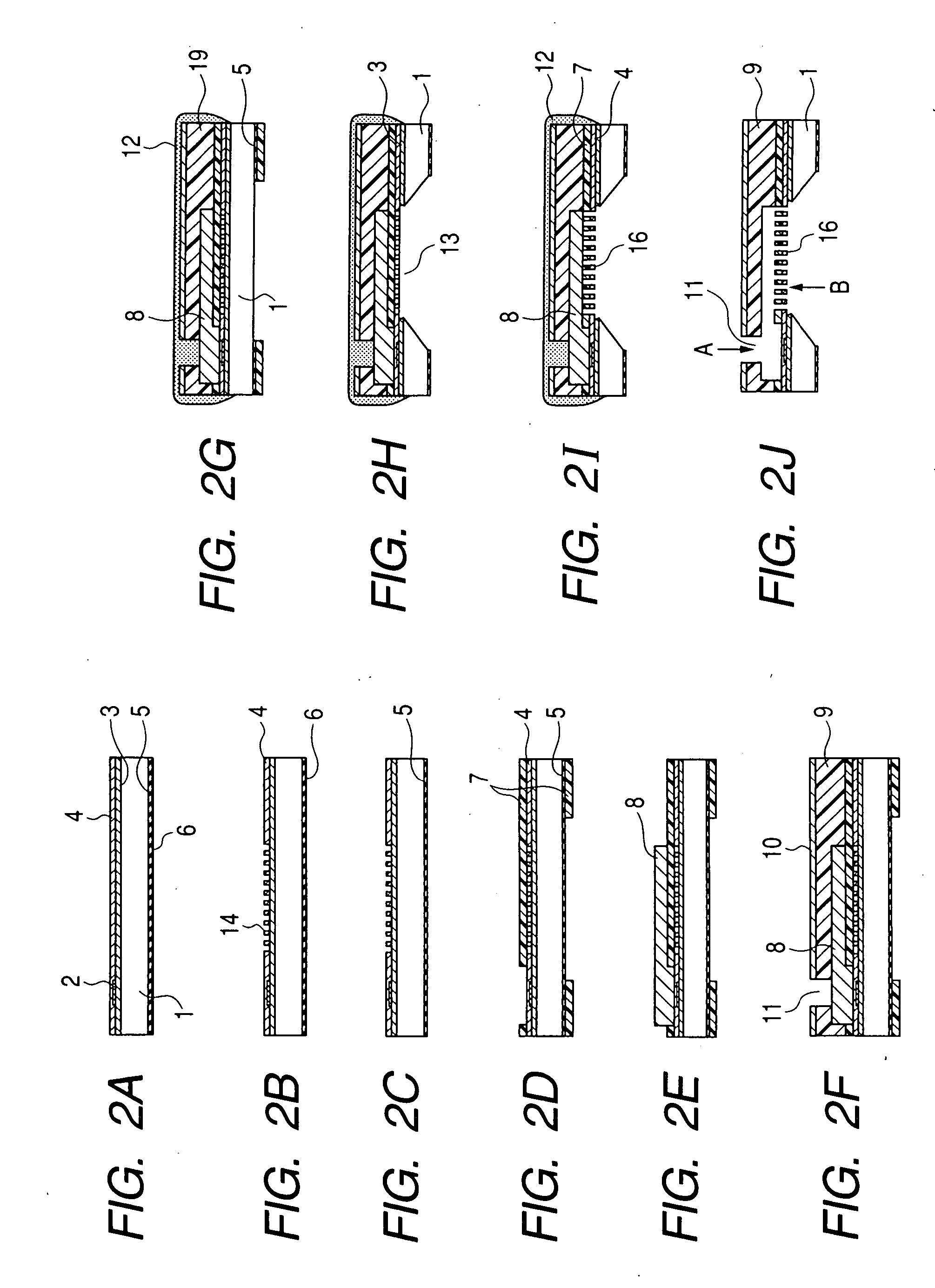
[0034] Next, steps of manufacturing an ink jet recording head according to a first example of the present invention will be described with reference to FIGS. 2A to 2J. FIGS. 2A to 2J are schematic sectional views showing the steps of manufacturing the ink jet recording head according to the first example of the present invention. It is to be noted that FIGS. 2A to 2J show sections in A-A line of FIG. 1B.

[0035] An Si substrate 1 shown in FIG. 2A has a crystal orientation of a plane. In the present example, the Si substrate 1 having the crystal orientation of the plane will be described as an example, but the plane orientation of the Si substrate 1 is not limited to this orientation.

[0036] An SiO2 film 3 which was an insulating layer was formed on the surface (first surface) of the Si substrate 1, a plurality of ink discharge pressure generation elements 2 constituted of heat generating resistors and the like were constituted on the film, and further an electric signal circuit (no...

second example

[0051] Next, steps of manufacturing an ink jet recording head according to a second example of the present invention will be described with reference to FIGS. 5A to 5J. FIGS. 5A to 5J are schematic sectional views showing the steps of manufacturing the ink jet recording head according to the second example of the present invention, and FIGS. 5A to 5J show sections in A-A line of FIG. 1B.

[0052] An Si substrate 21 shown in FIG. 5A has a crystal orientation of a plane. Even in the present example, the Si substrate 21 having the crystal orientation of the plane will be described as an example, but the plane orientation of the Si substrate 21 is not limited to this orientation.

[0053] An etching-proof mask 25 and a polysilicon film 26 constituted of insulating films such as SiO2 and SiN films were formed over the whole back surface (second surface) of the Si substrate 21, and an SiO2 film 23 was formed into a film thickness of 1.1 μm as an insulating layer on the surface (first surfac...

third example

[0067]FIG. 6 is a sectional view showing an ink jet recording head according to a third example of the present invention.

[0068] In the ink jet recording head of the present example, in a coating resin layer (nozzle forming member) 49 and a close contact enhancing layer 47 disposed on a first surface (upper surface) of an Si substrate 41, a portion existing in a middle area of an ink supply port 53 constitutes a support portion 60 which supports a membrane filter structure 56. The support portion 60 can be easily constituted by appropriately changing a shape of the pattern layer in the steps of manufacturing the ink jet recording head described in the first and second examples. Accordingly, for example, when ink flows into a nozzle channel from the ink supply port 53 with great force, the membrane filter structure 56 can be prevented from being pushed and broken by the ink. Therefore, strength of the membrane filter structure 56 against physical breakage can be enhanced.

[0069] It i...


PUM


Abstract

A method of manufacturing an ink jet head which discharges ink, comprising: a step of preparing a silicon substrate; a step of forming a membrane having a layer in which a plurality of holes are disposed to constitute a filter mask, and a layer with which a first surface is coated in such a manner that the first surface is not exposed from the plurality of holes on the first surface of the substrate; a step of forming a close contact enhancing layer on the membrane formed on the substrate; a step of forming a channel constituting member on the close contact enhancing layer to constitute a plurality of discharge ports and a plurality of ink channels communicating with the plurality of discharge ports; a step of forming an ink supply port communicating with the plurality of ink channels in the silicon substrate by anisotropic etching from a second surface facing the first surface of the substrate; and a step of forming a filter in a portion of the close contact enhancing layer positioned in an opening of the ink supply port using the layer of the membrane in which a plurality of holes are disposed as the mask.

Description

BACKGROUND OF THE INVENTION [0001] 1. Field of the Invention [0002] The present invention relates to a method of manufacturing an ink jet recording head for discharging liquid droplets to perform recording, an ink jet recording head, and an ink jet cartridge, concretely to a method of manufacturing an ink jet recording head comprising a filter, an ink jet recording head, and an ink jet cartridge. [0003] 2. Related Background Art [0004] In recent years, to miniaturize an ink jet recording head, and raising a density of heads, a method has been proposed in which an electric control circuit for driving an ink discharge pressure generation element is built in a substrate using a semiconductor manufacturing technique. In order to supply ink to a plurality of discharge ports, the ink jet recording head is structured such that nozzles are passed through the substrate from the back surface of the substrate, and connected to a common ink supply port, and the ink is supplied to the respective...

Claims


Application Information

Patent Timeline
Patent Type & Authority Applications(United States)
IPC IPC(8): B41J2/045B41J2/055B41J2/16
CPCB41J2/1603B41J2/1628B41J2/1629B41J2/1631B41J2002/14475B41J2/1639B41J2/1642B41J2/1645B41J2002/14403B41J2/1635B41J2/16
Inventor FUJII, KENJIKOYAMA, SHUJIOSUMI, MASAKINAGATA, SHINGOYAMAMURO, JUNTAGAWA, YOSHINORIMURAYAMA, HIROYUKIURAYAMA, YOSHINOBU
Owner CANON KK
Why Eureka
Try Eureka