
Porous honeycomb structure

a honeycomb structure and porous technology, applied in the field can solve the problems of increasing pressure loss, demanding the lengthening of trapping time, and promoting degradation of porous honeycomb structure, so as to achieve effective use of catalysts, improve purification performance, and effectively raise the effect of soot trapping efficiency

Active Publication Date: 2005-06-09
NGK INSULATORS LTD
View PDF6 Cites 32 Cited by
  • Summary
  • Abstract
  • Description
  • Claims
  • Application Information

AI Technical Summary

Benefits of technology

[0016] The present invention has been developed in consideration of the above-described problems, and an object thereof is to provide a porous honeycomb structure which is capable of effectively raising a trapping efficiency of soot or the like, improving a purifying performance by effective use of a catalyst, lowering a pressure loss, and lengthening a trapping time and which is further capable of improving a dissolved loss limit at the time of filter regeneration and an isostatic strength.
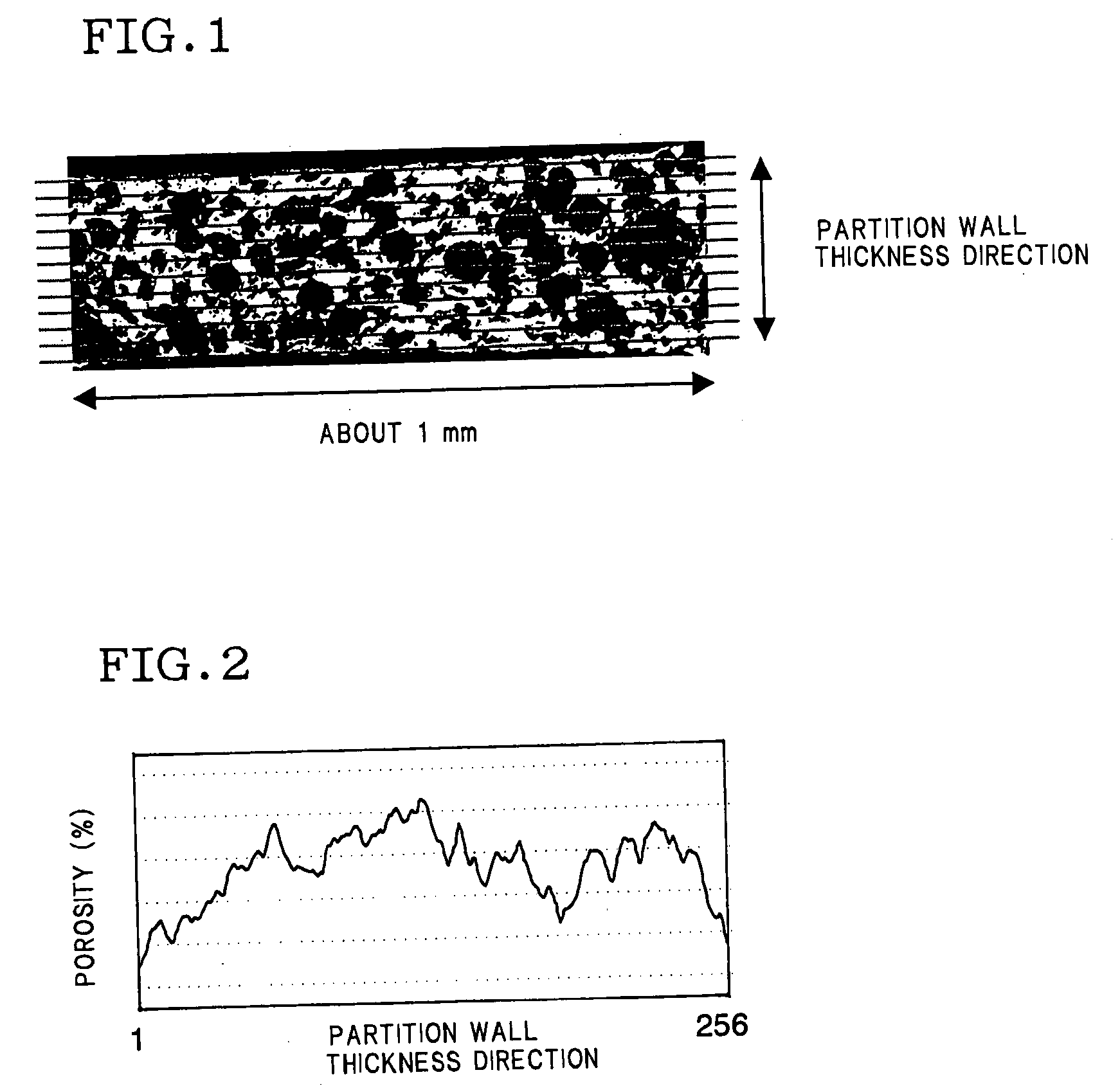
[0017] Moreover, as a result of intensive researches for achieving the object by the present inventor, findings have been obtained that when a honeycomb structure is manufactured by use of clay containing a foamed foaming resin added thereto, the honeycomb structure is obtained having a high porosity, including a large number of pores opened / formed in partition wall surfaces, and having a pore distribution in which a partition wall developed length ratio is not less than a specific value with respect to the whole porosity. It has been found that according to the honeycomb structure, the above-described conventional problems can be solved, and the present invention has been completed.

Problems solved by technology

When a certain or more amount of soot is deposited on pores opened in the surfaces of the partition walls, the pressure loss rapidly increases.
However, when this regeneration step is performed with a high frequency, degradation of the porous honeycomb structure is promoted.
Moreover, in the honeycomb structure, the distribution of the pores inside the partition walls, except a ratio of the pores opened in the surface of the partition wall with respect to the porosity of the whole partition wall, is not considered, and demands for the lengthening of the trapping time, the raising of the trapping efficiency, the improving of the purifying performance, and the lowering of the pressure loss have not been sufficiently satisfied.
However, also in this honeycomb structure, the ratio of the pores opened in the partition wall surface with respect to the porosity of the whole partition wall has not been considered.
Therefore, there is little organic foaming agent resulting in the opened surface of the partition wall just after extrusion molding.
As a result, in the honeycomb structure, the pore distribution of the partition wall in a thickness direction has a deviation, and the demands for the raising of the trapping efficiency, the lengthening of the trapping time, and the lowering of the pressure loss have not been sufficiently satisfied.
Since the amount of the catalyst supported inside the partition walls is very large because of the deviation of the pore distribution, an effective use ratio actually contributing to a purifying reaction is small, and a sufficient purifying performance has not been obtained.
Furthermore, when the porosity of the whole partition wall is further raised in order to solve the problem, there has been a problem that a local dissolved loss on the partition wall at the time of the filter regeneration is caused by the decrease of the isostatic strength or the thermal capacity.
The demands for the effective raising of the trapping efficiency, the lengthening of the trapping time, the improving of the purifying performance, and the lowering of the pressure loss are not sufficiently satisfied.
When the porosity of the whole partition wall is further raised, there has been a problem that the local dissolved loss of the partition wall at the time of the filter regeneration is caused by the decrease of the isostatic strength or the thermal capacity.

Method used


Image

  • Porous honeycomb structure
  • Porous honeycomb structure
  • Porous honeycomb structure

Examples


examples 2 to 10

, AND COMPARATIVE EXAMPLES 1 TO 8

[0079] Honeycomb structures (honeycomb filters) were obtained in the same manner as in Example 1 except that cordierite raw materials and pore formers having compositions shown in Tables 1 and 2 were used in Example 1.

[0080] (Evaluation Results)

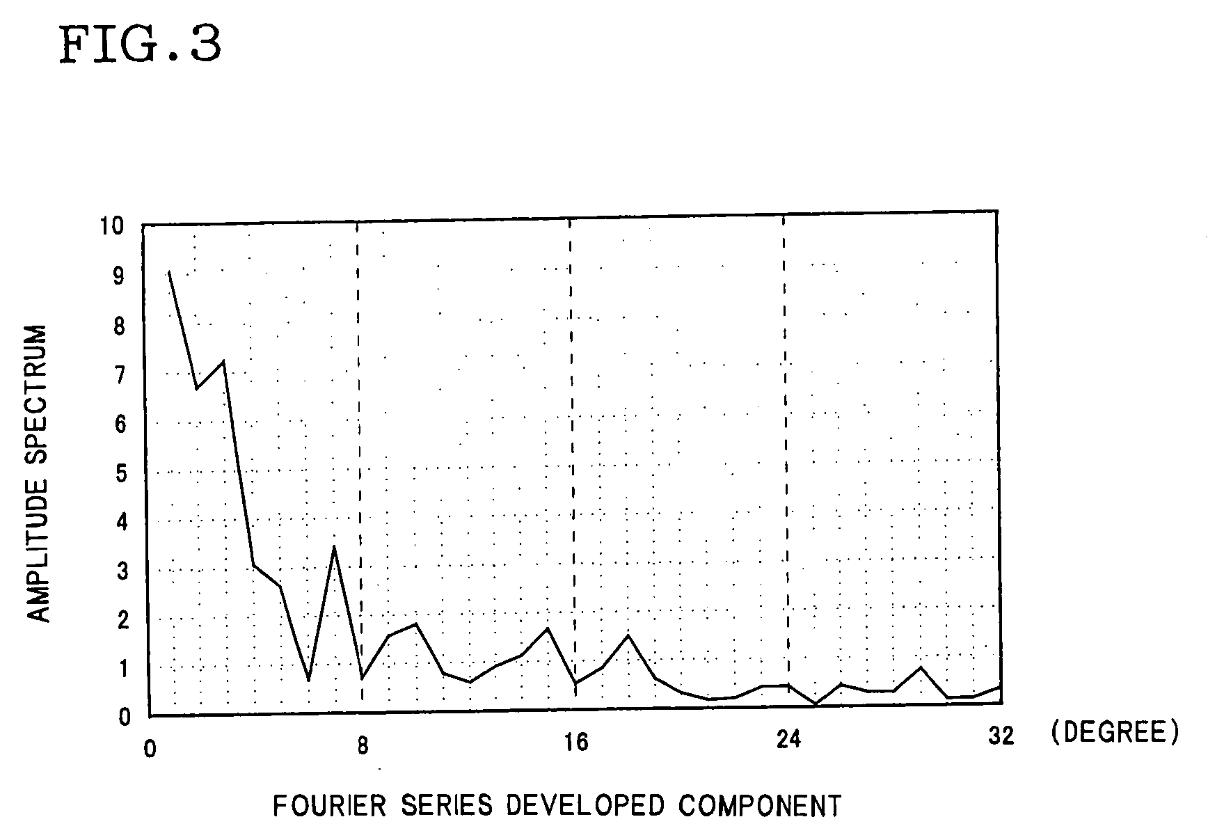
[0081] In each of honeycomb structures of Examples 1 to 10 in which 2 to 3.5 parts by mass of a foamed foaming resin was added as a pore former as shown in Tables 2, 3, an average pore diameter of partition walls was 16.0 to 34.6 μm, and a porosity was 55.5 to 72.0%. In any example, a pore distribution of the obtained honeycomb structure satisfied conditions of Condition Formulas (1) and (3) as shown in FIGS. 4 and 5. Even in the honeycomb structures of Examples 1 and 7 in which comparatively coarse talc and silica raw materials were used, the conditions of these relation formulas were satisfied, and this was supposedly because the foamed foaming resin expanded in the partition walls immediately after the fo...

example 11

[0090] A honeycomb structure (catalyst carrier) having a size: φ229.0 mm×L 152.0 mm, a partition wall thickness: 300 μm, and a cell density: 46.5 cells / cm2 was manufactured in the same manner as in Example 1 except that a step of plugging through-holes was not performed in Example 1.


PUM

PropertyMeasurementUnit
pore diameteraaaaaaaaaa
porosityaaaaaaaaaa
lengthaaaaaaaaaa

Abstract

A porous honeycomb structure includes: a plurality of partition walls containing cordierite as a main component and constituted of a porous ceramic having a porosity of 55 to 75% and an average pore diameter of 15 to 35 μm, wherein the partition walls have a pore distribution represented by the following condition formula (1): Lr>0.3×P / 100+0.91  (1), “in the above condition formula (1), Lr means an average developed length ratio, and P means a porosity obtained from a total pore volume measured by a mercury press-in type porosimeter, assuming that a true specific gravity of cordierite is 2.52 g / cc.”The porous honeycomb structure is capable of effectively achieving raising of a trapping efficiency of soot or the like, lowering of a pressure loss, improving a purifying performance by effective use of a catalyst, and lengthening a trapping time, and is additionally capable of improving a dissolved loss limit at the time of filter regeneration, and an isostatic strength.

Description

TECHNICAL FIELD [0002] The present invention relates to a porous honeycomb structure. The present invention relates particularly to a porous honeycomb structure applicable as a filter for purifying an exhaust gas, which is capable of effectively lengthening a trapping time, raising a trapping efficiency, and lowering a pressure loss, when a pore distribution of partition walls is controlled and which is further capable of preventing a dissolved loss at the time of filter regeneration or improving an isostatic strength, and as a catalyst carrier which is capable of effectively improving a purifying performance and lowering a pressure loss and which is superior in isostatic strength. BACKGROUND ART [0003] In recent years, influences of particulate matters or NOx exhausted from an engine for an automobile, especially a diesel engine or the like onto environments have been brought into the public eye, and various uses of porous honeycomb structures as important means for removing these ...

Claims


Application Information

Patent Timeline
Patent Type & Authority Applications(United States)
IPC IPC(8): B01D39/20F01N3/02B01D46/00B01D46/24B01D53/86B01D53/94B01J21/14B01J35/04B01J35/10B01J37/00B01J37/02C04B38/00C04B38/06F01N3/022F01N3/035F01N3/28
CPCB01D39/2068Y10T428/24149B01D46/2429B01D46/2444B01D46/2466B01D46/2474B01D2046/2433B01D2046/2437B01D2046/2496B01J21/14B01J35/04B01J35/1076B01J35/108B01J37/0018B01J37/0246C04B38/0006C04B38/007C04B2111/00198C04B2111/00793F01N3/0222F01N3/035F01N3/2828F01N2330/30B01D46/2425C04B35/195C04B38/0054C04B38/0074B01D46/2498B01D46/24492B01D46/24491B01D46/24494B01D46/2482B01J35/56B01J35/66B01J35/657
Inventor NOGUCHI, YASUSHINISHI, HIDEAKISUENOBU, HIROYUKI
Owner NGK INSULATORS LTD
Learn More