Vehicular drive system and driving method

a technology of vehicle drive and transmission control, which is applied in the direction of hybrid vehicles, gearing, transportation and packaging, etc., can solve the problems of increasing the likelihood of gear noise, mass, and weight, and achieves the effect of reducing the output of the shifting power unit, increasing the number of gears, and high economic

Active Publication Date: 2005-06-09
HITACHI ASTEMO LTD
View PDF7 Cites 21 Cited by
  • Summary
  • Abstract
  • Description
  • Claims
  • Application Information

AI Technical Summary

Benefits of technology

[0007] It is an object of the present invention to eliminate the above-mentioned inconveniences and provide a vehicular drive system which provides a high economical effect.
[0008] The vehicular drive system of the present invention is characterized in that a shifting power unit is not merely provided between an input shaft and an intermediate shaft, but a mechanism for transferring of power from the input shaft to both first and second intermediate shafts and for cutting off the power is provided; one side of the shifting power unit is connected to the input shaft, while an opposite side thereof is connected to a power transfer switching clutch; and the shifting power unit is connected to the first or the second intermediate shaft through a reduction mechanism. Thereby, the output of the shifting power unit can be decreased while minimizing an increase in the number of gears.
[0009] According to the present invention, a gear ratio different from that of reduction gears in a transmission is provided in common, whereby the number of gears used can be decreased without increasing the capacity of a motor which is high in cost, and thus a more outstanding economical effect can be obtained.
[0010] Moreover, since the shifting power unit is provided between the first or the second intermediate shaft and the input shaft, a vehicle driving power unit can be started without engaging a gear connected to an output shaft and hence there can be attained a highly quiet drivability without transfer of a starting shock to the vehicle.

Problems solved by technology

According to this construction, however, the number of gears used becomes twice as large, with a consequent likelihood of an increase of gear noise, mass, and weight.

Method used


Image

  • Vehicular drive system and driving method
  • Vehicular drive system and driving method
  • Vehicular drive system and driving method

Examples


Embodiment Construction

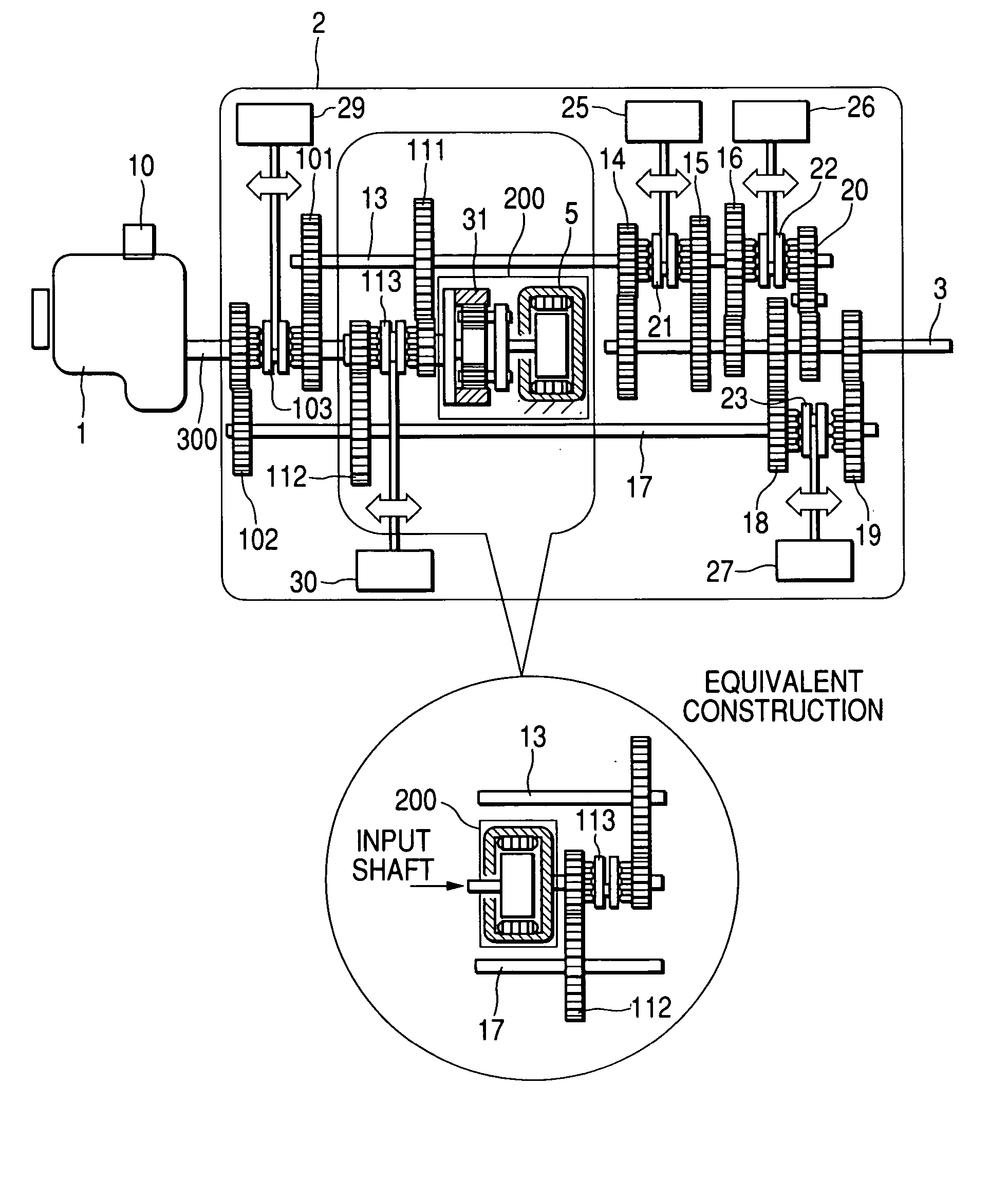
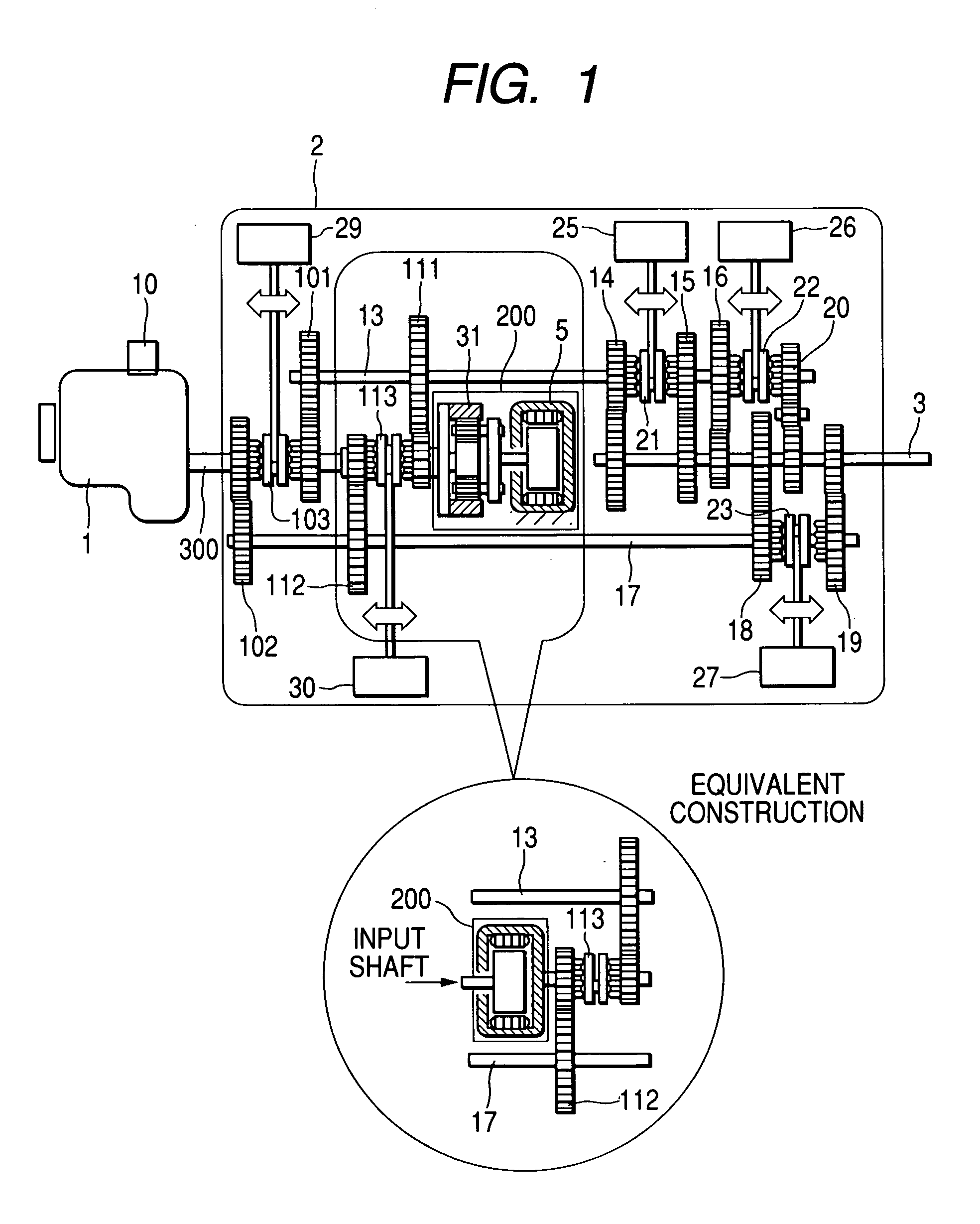
[0024]FIG. 1 is a construction diagram showing a first embodiment of the present invention. A vehicle driving power unit 1 is coupled to an input shaft 300 of a transmission 2. The vehicle driving power unit 1 is generally an internal combustion engine, but may be a power unit having a rotary shaft such as a motor. An output shaft 3 of the transmission 2 is connected to wheels (not shown). With a dog clutch 103, the input shaft 300 can transmit a driving force to a first intermediate shaft 13 and a second intermediate shaft 17 and cut off the supply of the driving force. When the intermediate shaft 13 is selected, it is engaged to the input shaft through a direct-coupling gear 101, while when the intermediate shaft 17 is selected, it is engaged to the input shaft through a direct-coupling gear 102. With shift gears 14, 15, 16, 18, 19, and 20, the first and second intermediate shafts are connected to the output shaft 3 through dog clutches 21, 22, and 23.

[0025] The above dog clutche...


PUM


Abstract

In a shift system wherein the transfer of power is performed using a motor, the smaller the gear ratio difference is, the smaller can be made the motor output. However, the number of gears must be increased in order to reduce the gear ratio. As the number of gears increases, the problem of gear noise becomes more serious. It is necessary to prevent both an increase in the number of gears and an increase of the motor output. In a vehicular drive system according to the present invention, a shifting power unit is not merely provided between a first intermediate shaft and a second intermediate shaft of a shift system which has the two intermediate shafts, but one side of a shifting power unit is connected to a vehicle driving power unit, while an opposite side thereof is connected to a power transfer switching clutch so as to be connected to the first or the second intermediate shaft through a reduction mechanism, whereby the output of the shifting power unit is decreased while minimizing an increase in the number of gears.

Description

CLAIM OF PRIORITTY [0001] The present application claims priority from Japanese application serial no. 2003-405310 filed on Dec. 4, 2003, the contents of which are hereby incorporated by reference into this application. BACKGROUND OF THE INVENTION [0002] The present invention relates to an automatic transmission, an automatic transmission control device, an automatic transmission control method, an automatic shift system, and a vehicle using the same. [0003] As a conventional automatic transmission there is used a planetary gear type or parallel-shaft type shift mechanism and there usually is adopted a method wherein a shift is performed by selectively engaging clutches provided individually in gear shift ranges of different transmission gear ratios (see, for example, Japanese Patent Laid-Open No. H10(1998)-89456). The applicant in the present case has proposed such a system as shown in Japanese Patent Application No. 2002-3561245 wherein a parallel-shaft type shift mechanism having...

Claims


Application Information

Patent Timeline
Patent Type & Authority Applications(United States)
IPC IPC(8): F16H3/12F16H3/093F16H61/04F16H61/08F16H61/682
CPCB60K6/365Y10T477/26B60W10/08B60W20/00B60W30/19F16H3/006F16H3/126F16H3/725F16H61/0403F16H61/682F16H61/70F16H2003/0818F16H2061/0422F16H2061/0433F16H2200/0052F16H2306/46F16H2306/50Y02T10/6221F16H2061/0496F16H2061/0492Y10T74/19251Y10T74/19284B60K6/48Y02T10/62B60W20/40
Inventor SAKAMOTO, HIROYUKIIBAMOTO, MASAHIKOKUROIWA, HIROSHI
Owner HITACHI ASTEMO LTD
Why Eureka
Try Eureka