

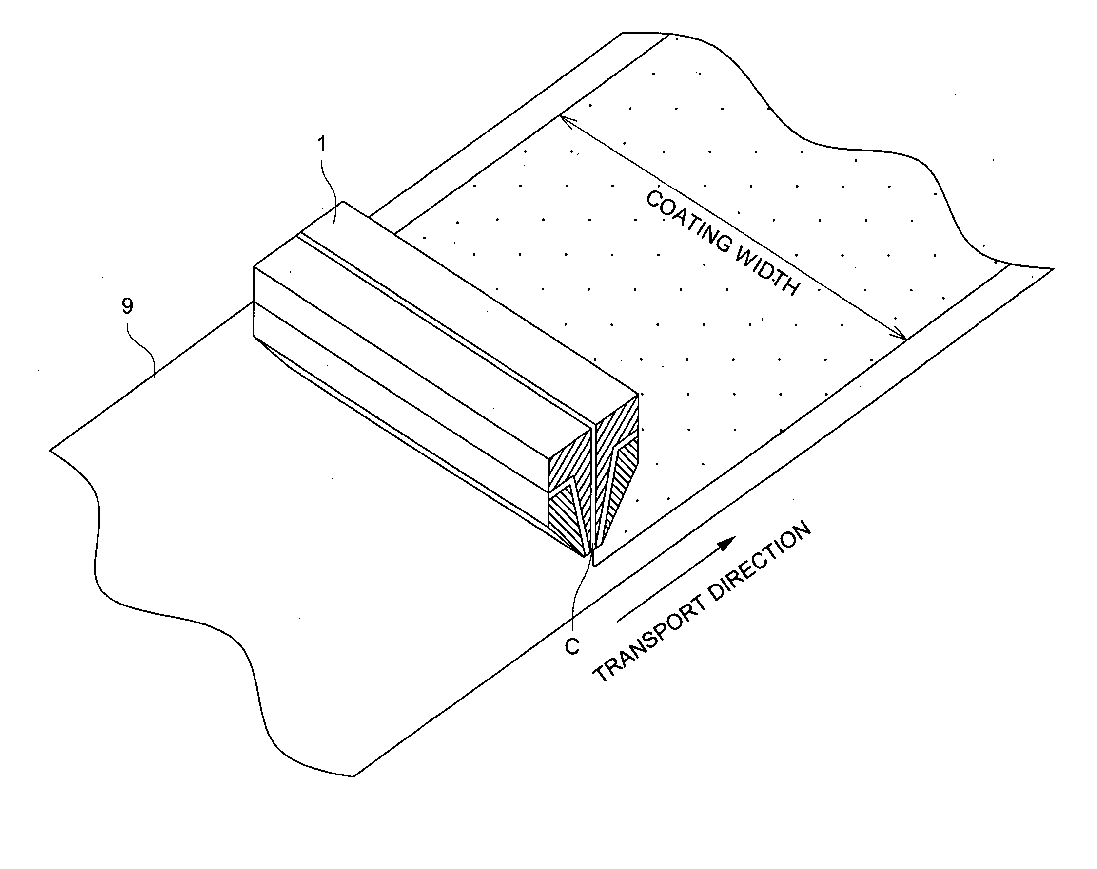
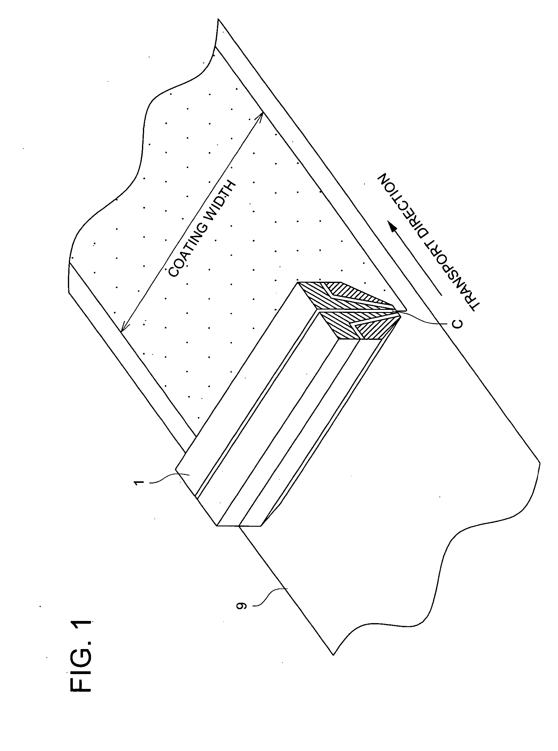
Coating apparatus and coating method
a coating apparatus and coating technology, applied in the direction of liquid surface applicators, spraying apparatus, liquid spraying apparatus, etc., can solve the problems of uneven cross-streak and/or spot coating, and many additives are often subject to various limitations
- Summary
- Abstract
- Description
- Claims
- Application Information
AI Technical Summary
Benefits of technology
Problems solved by technology
Method used
Image

Examples
example 1
Preparation of Member 1 to be Coated
[0123] Member 1 to be coated is prepared by forming a porous ink absorptive layer, which is constituted of 4 layers, as a constituent layer on a support.
[Preparation of Support]
[0124] Low density polyethylene having a density of 0.92 was coated at a thickness of 35 μm by an extrusion coating method on the back side surface of a paper substrate for photography having a moisture content of 6% and a basis weight of 200 g / m2. Next, low-density polyethylene containing 5.5% of anatase type titanium dioxide and having a density of 0.92 was coated at a thickness of 40 μm by an extrusion coating method on the front side surface, resulting in a preparation of a support the both surfaces of which are covered with polyethylene. An under-coat layer comprising polyvinyl alcohol was coated to make 0.03 g / m2 on the front side after having been subjected to corona discharge as well as a latex layer was coated to make 0.12 g / m2 on the back side after having bee...
example 2
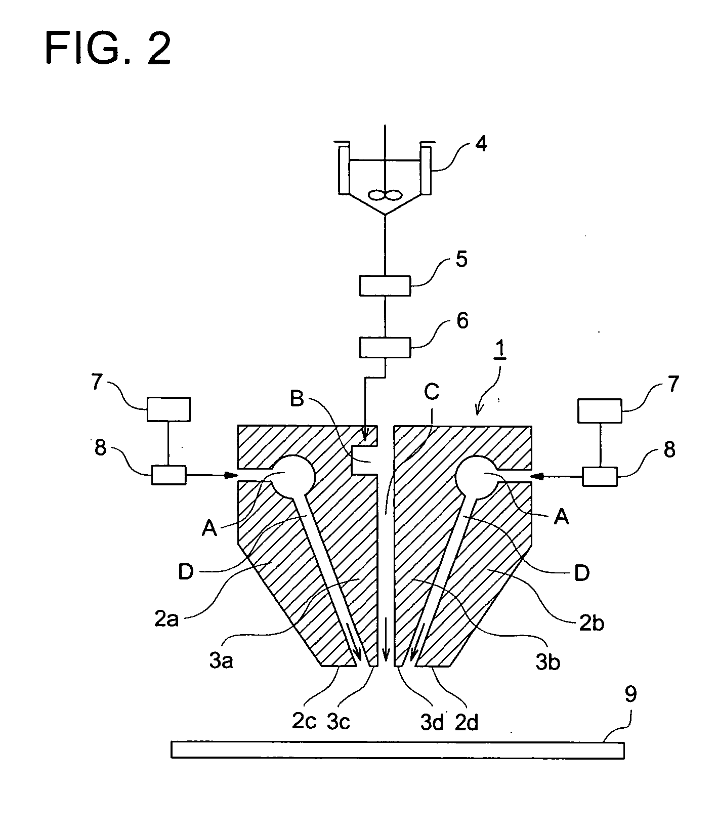
[0149] Coatings 201-204 were performed in a similar manner to coating 103 (α=180 degree, β=30 degree) described in example 1, except that angles β formed between a coating solution ejecting outlet of a coating solution nozzle and a gas gushing outlet of a gas nozzle were changed to 15 degree, 45 degree, 60 degree and 75 degree, respectively, and the state of the bottom plane portion of a slot nozzle spraying apparatus, the flying state of a coating solution and the coated surface quality were visually observed, together with coating 103 performed in example 1, to obtain the following results.
Coating 201 (β=15 Degree)
[0150] No over-coat solution liquid drops adhered on bottom planes 2c and 2d of outer die blocks resulting in a uniform coating property.
Coating 103 (β=30 Degree)
[0151] No over-coat solution liquid drops adhered on bottom planes 2c and 2d of outer die blocks-resulting in a uniform coating property.
Coating 202 (β=45 Degree)
[0152] No over-coat solution liquid drop...
example 3
[0156] Coatings 301-304 were performed in a similar manner to coating 103 (L1, L2=0.5 mm) described in example 1, except that each width L1 and L2 of the bottom planes of inner die blocks was changed to 0.05 mm, 1.0 mm, 1.5 mm and 2.0 mm, and coated surface quality was visually observed, together with coating 103 performed in example 1, to obtain the following results.
Coating 301 (L1, L2=0.05 mm)
[0157] No streak defects and spot defects are observed on the obtained coated layer surface.
Coating 103 (L1, L2=0.5 mm)
[0158] No streak defects and spot defects are observed on the obtained coated layer surface.
Coating 302 (L1, L2=1.0 mm)
[0159] Very weak random longitudinal streak unevenness is observed when the coated layer surface is precisely observed, however, no spot defects are observed, which is practically allowable quality.
Coating 303 (L1, L2=1.5 mm)
[0160] Strong longitudinal streak defects are caused on the coated layer surface, which is practically problematic quality....
PUM
 Abstract
Description
Claims
Application Information