Thermoelectric module with directly bonded heat exchanger

a heat exchanger and thermal module technology, applied in the direction of thermoelectric devices with peltier/seeback effect, basic electric elements, electric apparatus, etc., can solve the problems of limited efficiency of conventional construction, brittleness of wafers and thermal stresses at the junction of the substrate and the thermoelectric material chips, and stiffness of ceramics and thermal stresses at the junction of the substrate and the thermoelectric semiconductors. , to achieve the effect of reducing the thermal resistance of the conventional substrate, improving thermal efficiency

Inactive Publication Date: 2005-06-09
FERROTEC USA CORP
View PDF5 Cites 88 Cited by
  • Summary
  • Abstract
  • Description
  • Claims
  • Application Information

AI Technical Summary

Benefits of technology

[0019] It is an object of the present invention to provide a thermoelectric module that has an improved thermal efficiency.
[0020] The present invention achieves these and other objectives by providing electrical junctions of either or both sides of a thermoelectric module directly bonded to a heat source or sink or an object to be thermally modified (that is, heated or cooled), thus reducing the thermal resistance of the conventional substrate and eliminating the associated thermal interface resistance. An electrically conductive material such as copper, aluminum or any other known electrical conductor exhibiting relatively high thermal conductivity can be used as the electrical junction between a pair of thermoelectric elements.
[0021] In one embodiment, the conductive junction is directly bonded to the heat exchanger or heat sink using adhesives or other material capable of adhering the conductive junction to the surface of the heat sink. The adhesives or other material must be a thermally conductive dielectric. The purpose of directly bonding the conductive junctions is to construct a thermoelectric module directly on the object that is being heated or cooled with a substrate on the opposite side of the module or to construct a module between two objects. An advantage of this construction will cause an improvement in the thermal performance of a module by reducing the thermal interface losses in a thermoelectric assembly.
[0022] The use of the present inventive module eliminates the need for separate structural substrates, therefore reducing the size of the thermoelectric module as well as increasing efficiency by eliminating interfaces between devices. The reduced size and increased efficiency provided by the present invention can be effectively used in applications such as automotive exhaust pipes and radiators where the thermoelectric device is built into the apparatus. Many other uses could be considered including steam pipes, process piping, ventilation systems, electronics cooling, miniature air coolers, etc.

Problems solved by technology

A disadvantage of using silicon wafers as a substrate is the brittleness of the wafer and the thermal stresses that occur at the junction of the substrate and the thermoelectric material chips.
A disadvantage of using a ceramic substrate is the stiffness of the ceramic and the thermal stresses that occur at the junction of the substrate and the thermoelectric semiconductor chips when thermally cycled.
While such devices work well, the efficiency is limited by the conventional construction.
This material has relatively poor thermal conductivity for example approximately 35 watts / m ° C. Since heat, which is transferred from the heat source to the heat sink, must pass through two substrates, both of which have poor conductivity, the efficiency of the device is reduced.
The main disadvantage in conventional thermoelectric use including the use of alumina substrates, polyimide substrates or any other substrates is the limited heat transfer from the heat source to the heat sink since the heat must pass through interface layers from heat source to the thermoelectric element and from the thermoelectric element to the heat sink.
Other disadvantages of current thermoelectric module technology require that the substrates be thick enough to withstand cracking.
Also, material costs for the thicker substrates are higher.

Method used


Image

  • Thermoelectric module with directly bonded heat exchanger
  • Thermoelectric module with directly bonded heat exchanger
  • Thermoelectric module with directly bonded heat exchanger

Examples


Embodiment Construction

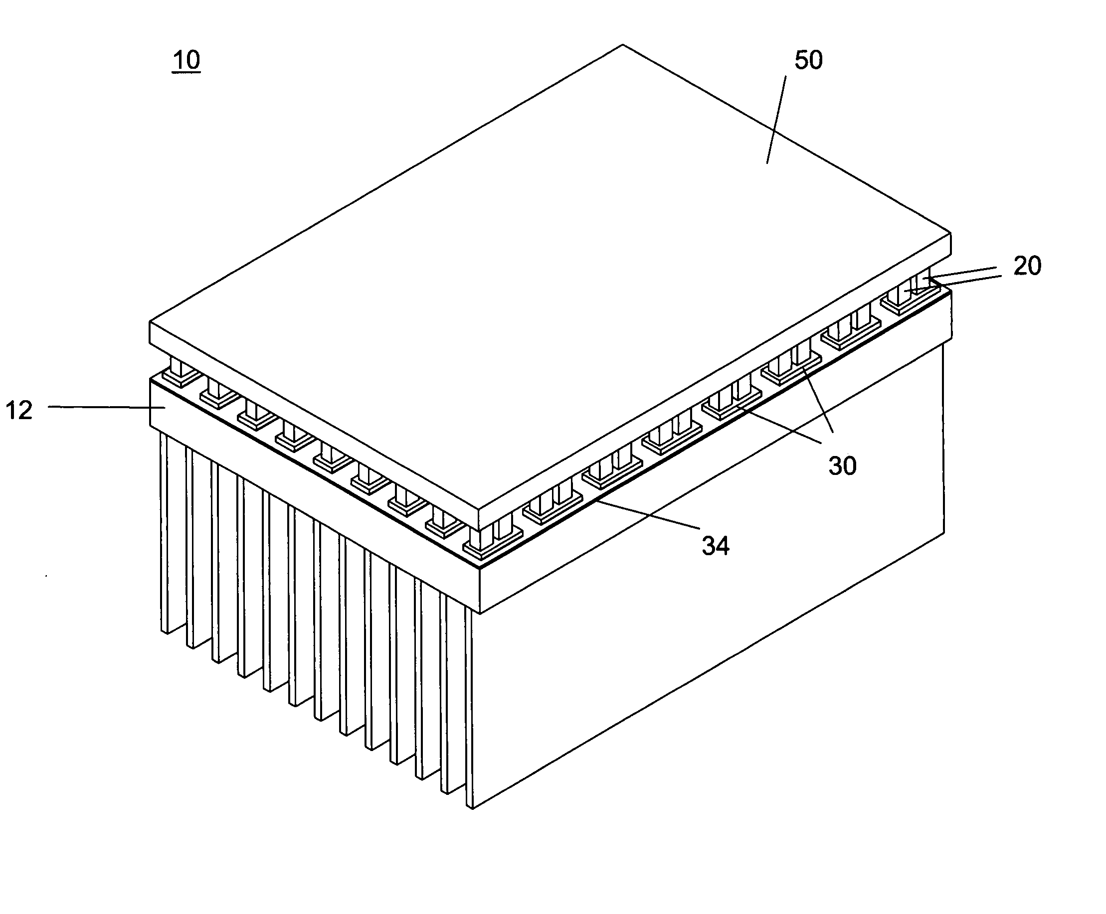
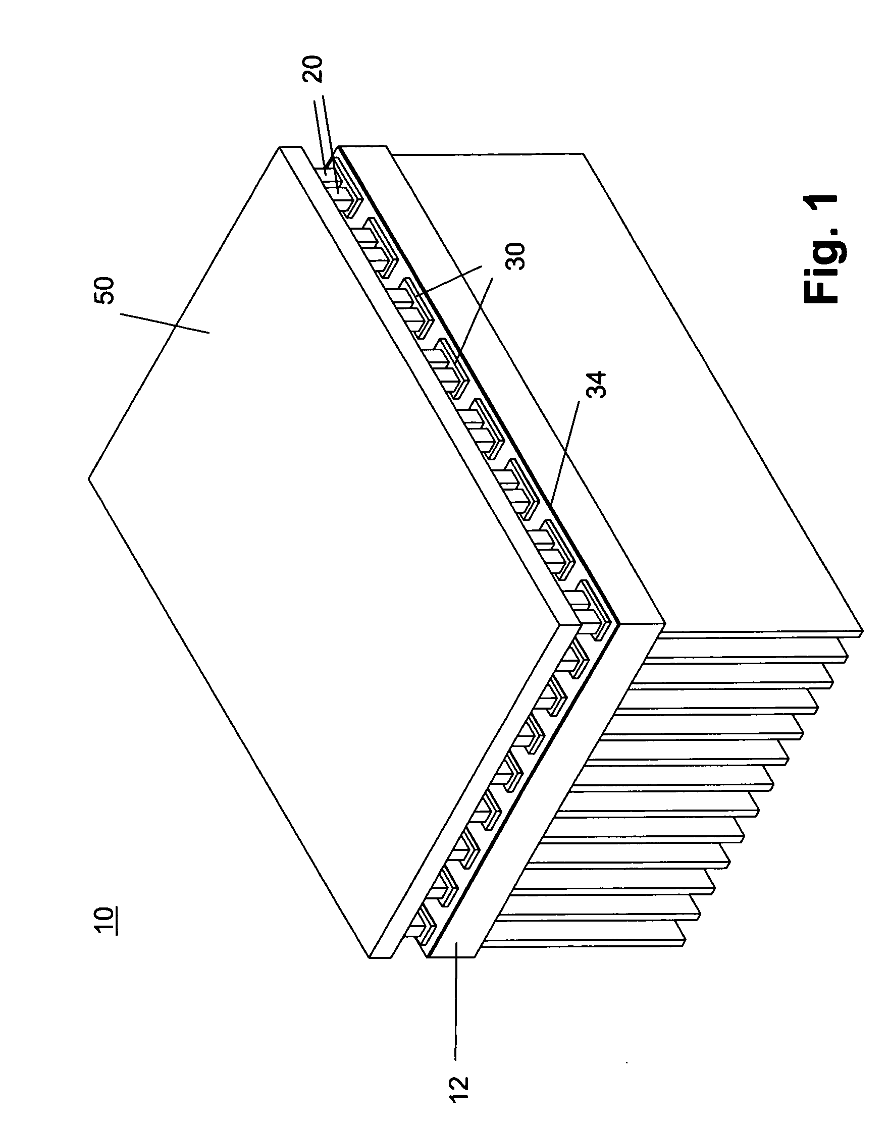
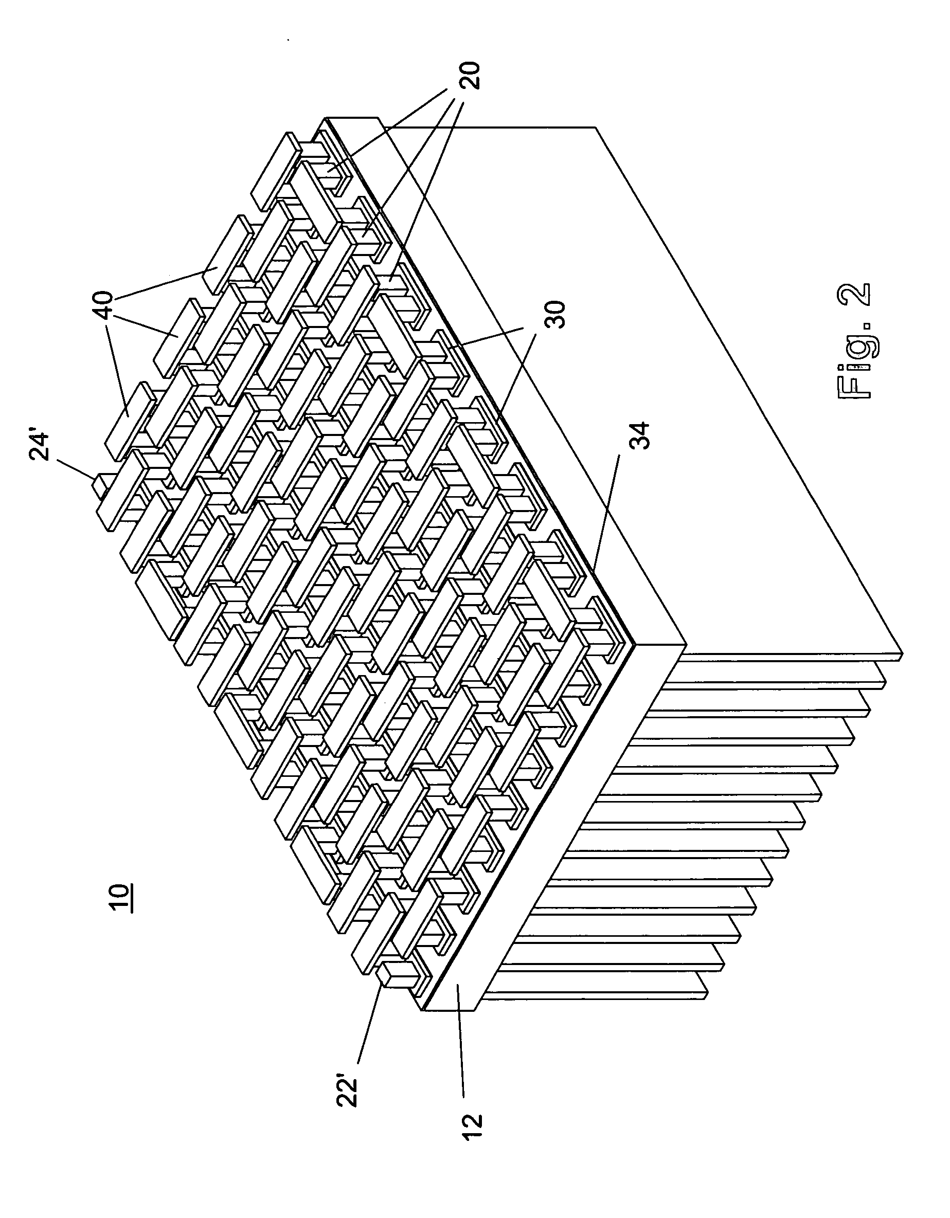
[0031] The preferred embodiment of the present invention is illustrated in FIGS. 1-8. FIG. 1 shows a thermoelectric module 10 of the present invention. Module 10 includes an object to be heated or cooled 12, a plurality of thermoelectric elements 20, a plurality of electrically conductive lower pads 30, a plurality of electrically conductive upper pads 40 (not shown), and a reinforcing substrate 50. Each of the plurality of electrically conductive lower pads 30 is directly bonded to a surface 14 of object 12 with a thermally conductive bonding material 34 that is covering at least the surface area of object 12 beneath the plurality of lower pads 30 defined by the perimeter pads of module 10. It is important to note that the thermoelectric module 10 of the present invention does not have a substrate between the object to be heated or cooled 12 and the electrically conductive pads 30 that would provide structural reinforcement to thermoelectric module 10 as provided in the prior art. ...


PUM


Abstract

A thermoelectric device with an improved thermal efficiency has an object to be heated or cooled having a surface, at least one electrically conductive lower pad bonded directly to the surface of the object using a thermally conductive dielectric material, at least one thermoelectric element coupled on one end to the electrically conductive pad, at least one electrically conductive upper pad coupled to an opposite end of the thermoelectric element, and electrical power connections coupled to the device.

Description

BACKGROUND OF THE INVENTION [0001] 1. Field of the Invention [0002] The present invention relates generally to heat transfer devices and methods of connecting such devices to objects to be heated or cooled. Particularly, the present invention relates to thermoelectric heat transfer devices. More particularly, the present invention relates to thermoelectric devices and a method of fabricating the same. [0003] 2. Description of the Prior Art [0004] Thermoelectric cooling was first discovered by Jean-Charles-Athanase Peltier in 1834, when he observed that a current flowing through a junction between two dissimilar conductors induced heating or cooling at the junction, depending on the direction of current flow. This is called the Peltier effect. Practical use of thermoelectrics did not occur until the early 1960s with the development of semiconductor thermocouple materials, which were found to produce the strongest thermoelectric effect. Most thermoelectric materials today comprise a c...

Claims


Application Information

Patent Timeline
Patent Type & Authority Applications(United States)
IPC IPC(8): H01L35/30
CPCH01L35/30H10N10/13
Inventor OTEY, ROBERT W.
Owner FERROTEC USA CORP
Why Eureka
Try Eureka