

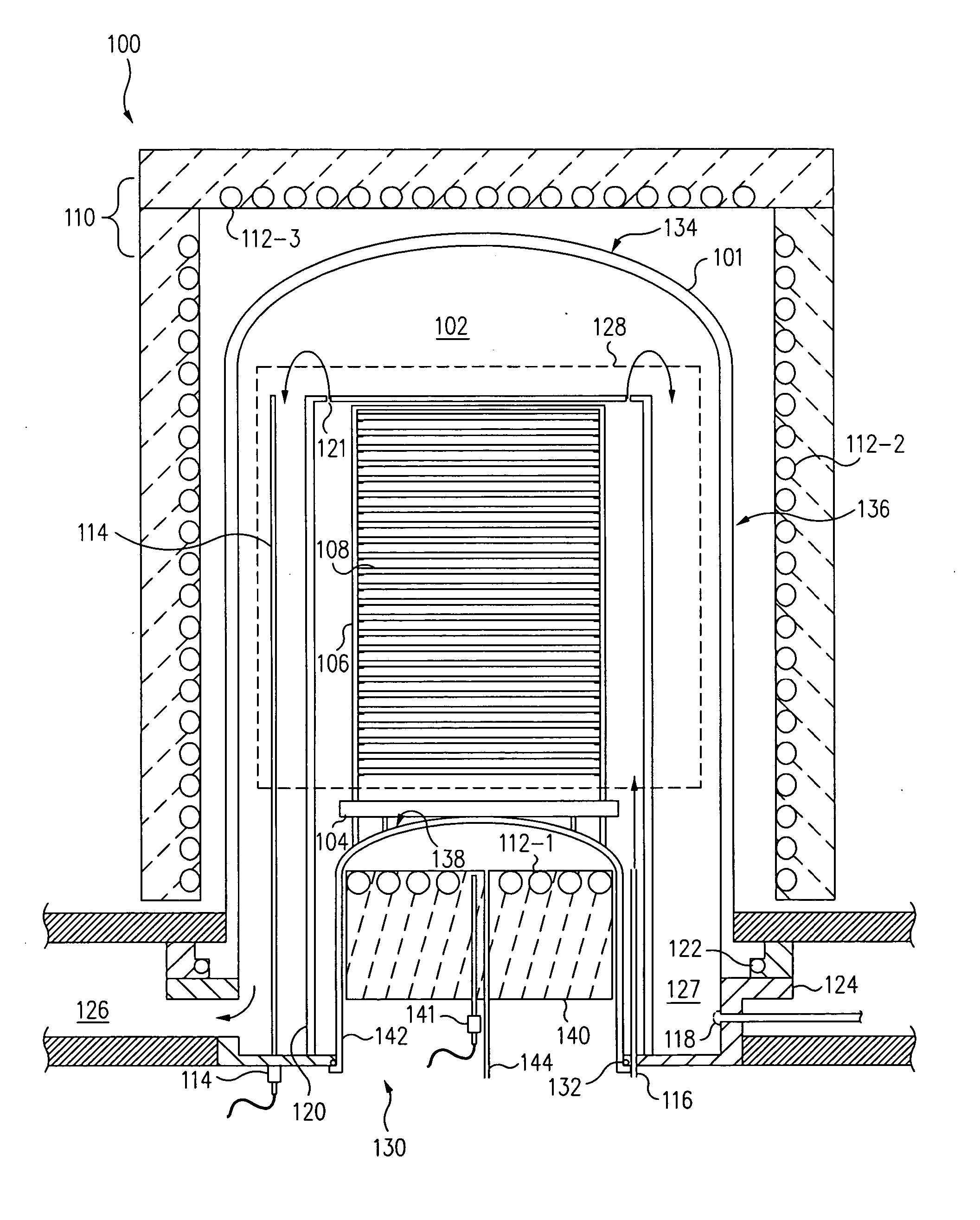
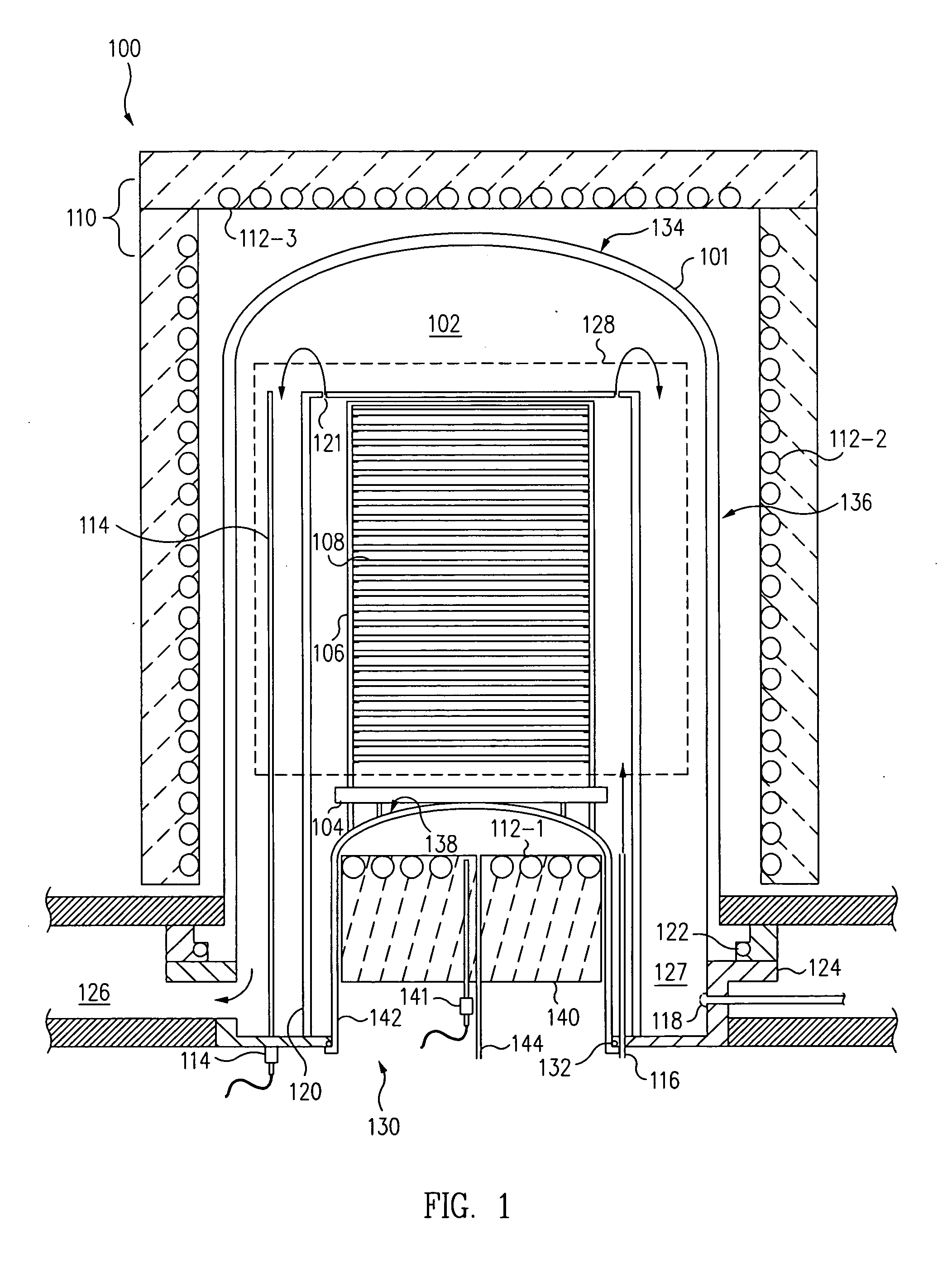
Thermal processing system with cross flow injection system with rotatable injectors
a technology of injection system and thermal processing system, which is applied in the direction of coating, chemical vapor deposition coating, metallic material coating process, etc., can solve the problems of increasing processing time, occupying a tremendous amount of space and power, and considerable time required both before processing
- Summary
- Abstract
- Description
- Claims
- Application Information
AI Technical Summary
Benefits of technology
Problems solved by technology
Method used
Image

Examples
example 1
[0124] This example illustrates deposition of silicon nitride using dichlorosilane (DCS) and NH3 gases. The deposition is performed in a thermal processing apparatus including an injection system of the present invention. The injection system comprises a first injection tubes for introducing DCS gas and a second injection tube for introducing NH3 gas. Each of the first and second injection tubes is provided with a plurality of ports or orifices for directing gas flow across the surface of each substrate.
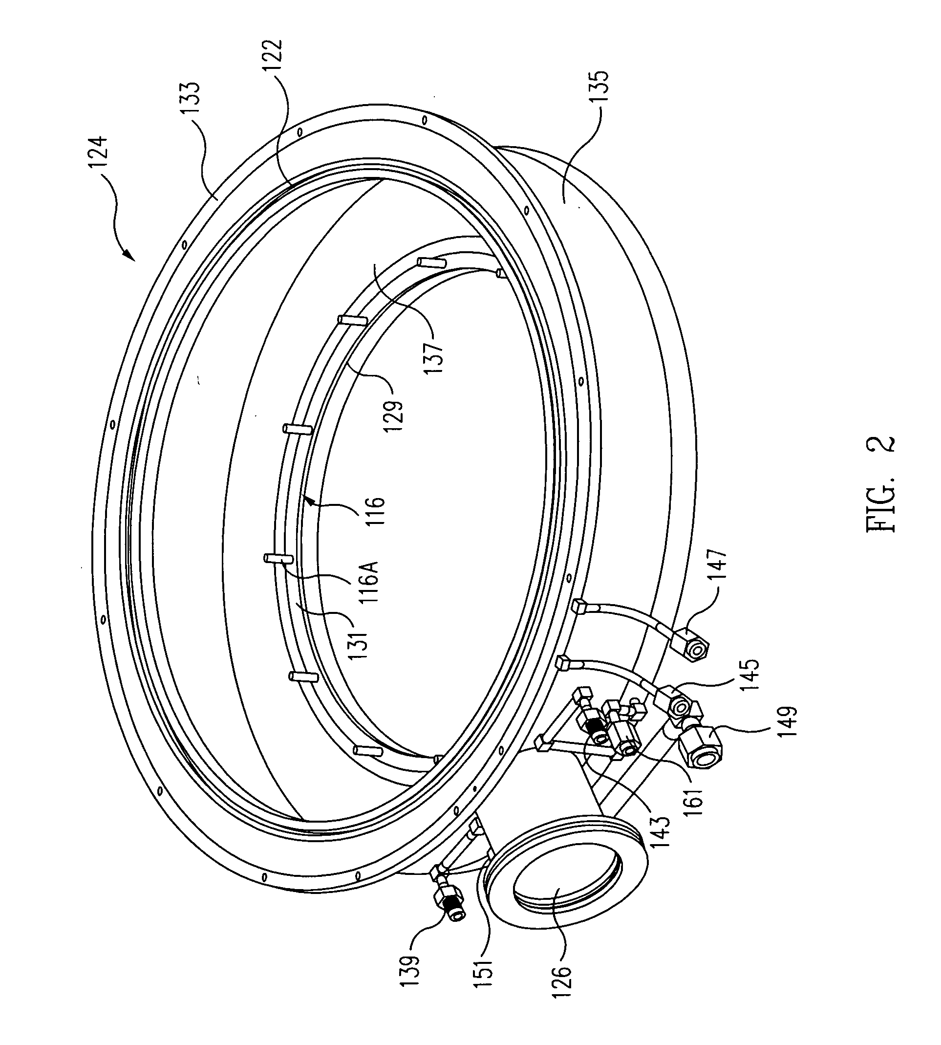
[0125] In one variation, the elongated tubes are rotated and adjusted so that the injection ports are oriented to face the inner surface of the liner. DCS and NH3 gases exiting the injection ports away from wafers and impinge the liner inner surface prior to flowing across the surface of each substrate.
[0126] In another variation, the elongated tubes are rotated and adjusted so that the injection ports are oriented to face the center of the substrate. DCS and NH3 gases exit the inj...
example 2
[0128] This example illustrates deposition of silicon nitride using bis tertiarybutylamino silane (BTBAS) and NH3 gases. The deposition is performed in a thermal processing apparatus including an injection system of the present invention. The injection system comprises a first injection tube for introducing BTBAS gas and a second injection tube for introducing NH3 gas. Each of the first and second injection tubes is provided with a plurality of ports or orifices for directing gas flow across the surface of each substrate.
[0129] In one variation, the elongated tubes are rotated and adjusted so that the injection ports are oriented to face the inner surface of the liner. BTBAS and NH3 gases exiting the injection ports away from wafers and impinge the liner wall prior to flowing across the surface of each substrate.
[0130] In another variation, the elongated tubes are rotated and adjusted so that the injection ports are oriented to face each other. BTBAS and NH3 gases exit the injecti...
example 3
[0132] This example illustrates deposition of aluminum oxide (Al2O3) using trimethyl aluminum (TMA) and ozone (O3) gases. The deposition is performed in a thermal processing apparatus including an injection system of the present invention. The injection system comprises a first injection tube for introducing TMA gas and a second injection tube for introducing O3 gas. Each of the first and second injection tubes is provided with a plurality of ports or orifices for directing gas flow across the surface of each substrate.
[0133] In one variation, the elongated tubes are rotated and adjusted so that the injection ports are oriented to face the inner surface of the liner. TMA and O3 gases exiting the injection ports away from wafers and impinge the liner wall prior to flowing across the surface of each substrate.
[0134] In one variation, the elongated tubes are rotated and adjusted so that the injection ports are oriented to face each other. TMA and O3 gases exit the injection ports and...
PUM
| Property | Measurement | Unit |
|---|---|---|
| temperature | aaaaa | aaaaa |
| temperature | aaaaa | aaaaa |
| time | aaaaa | aaaaa |
Abstract
Description
Claims
Application Information