Reaction vessel and reaction apparatus

a reaction vessel and reaction technology, applied in the field of reaction vessels and reaction apparatus, can solve the problems of difficult to achieve the goal of minimizing the amount of reaction solution, reaction to a halt, and the time required for pcr by using a conventional pcr reaction apparatus and pcr reaction vessel

Inactive Publication Date: 2005-06-09
PRECISION SYST SCI
View PDF1 Cites 37 Cited by
  • Summary
  • Abstract
  • Description
  • Claims
  • Application Information

AI Technical Summary

Benefits of technology

[0016] In view of this, a first object of the present invention is to provide a reaction vessel, reaction apparatus, and method with which a reaction can be automated without requiring centrifugation when a reaction solution is held in a reaction chamber, the temperature of the reaction solution h

Problems solved by technology

However, with a conventional PCR reaction apparatus and PCR reaction vessel, since the object is to perform a PCR by means of typical temperature control in which a reaction is repeated for 30 to 40 cycles, with each cycle comprising 30 seconds at 95° C., 30 seconds at 65° C., and 1 minute at 72° C., it is difficult to achieve the goal of minimizing the time required for the PCR by using a conventional PCR reaction apparatus and PCR reaction vessel.
Also, with a conventional PCR reaction apparatus and PCR reaction vessel, if the amount of specimen (reaction solution) is too small, the solvent (ordinarily water) in the reaction solution may evaporate during the PCR, bringing the reaction to a halt.
Because of the large contact area between air and the reaction solution in the reaction chamber (such as a micro-tube or micro-titer plate well) in which the PCR proceeds, the solvent in the reaction solution is in an environment in which it is prone to evaporation, and since the temperature of the walls inside the reaction chamber is not uniform, some portions of the walls inside the reaction chamber are lower in temperature than the reaction solution (such as the upper part of a micro-tube or upper part of a micro-titer plate well), so the evaporated solvent ends up being liquefied in these area

Method used


Image

  • Reaction vessel and reaction apparatus
  • Reaction vessel and reaction apparatus
  • Reaction vessel and reaction apparatus

Examples


first embodiment

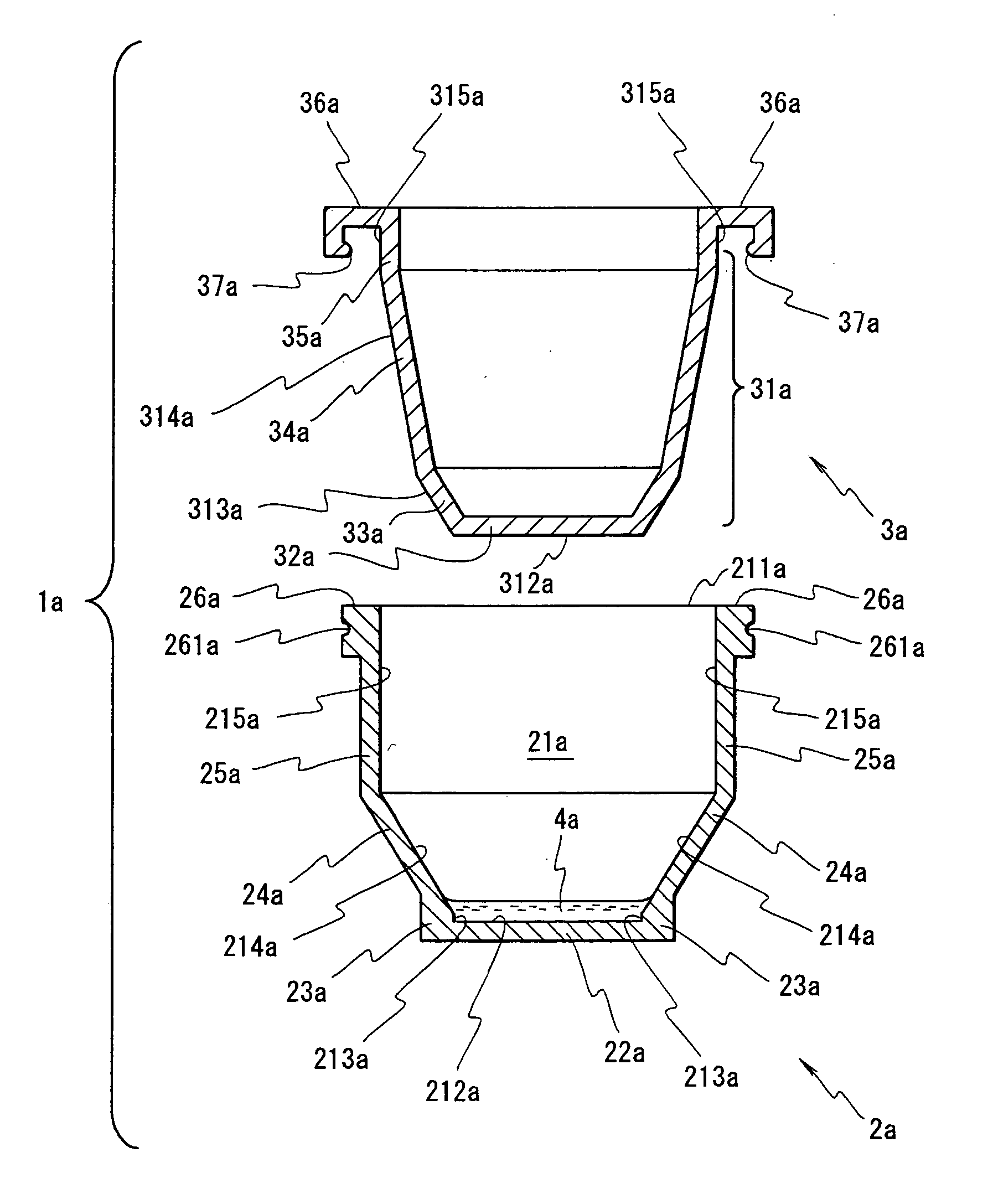
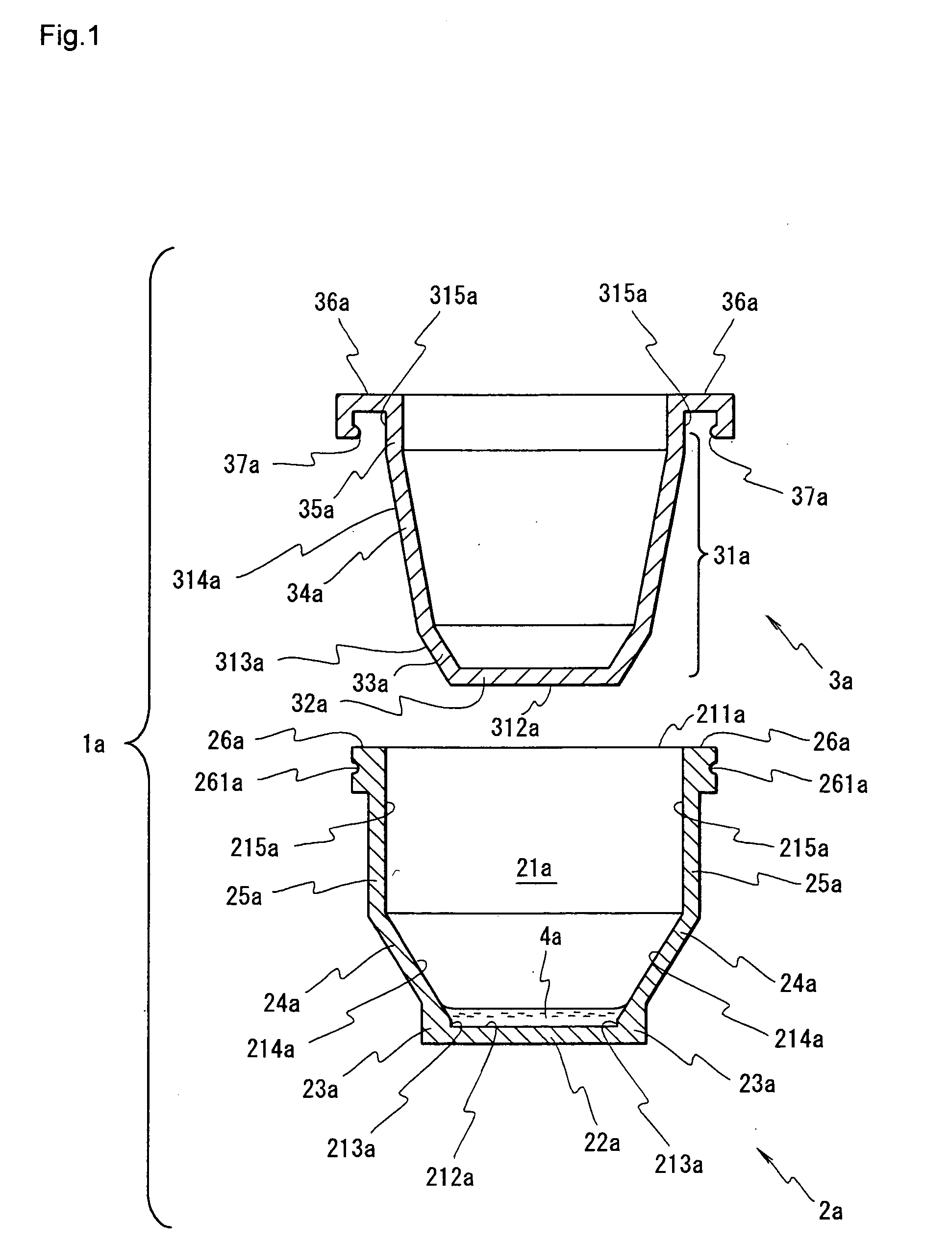
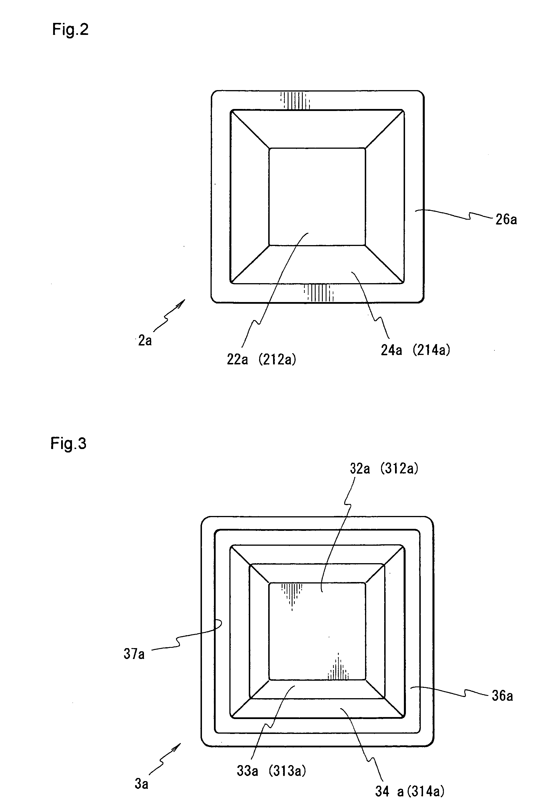
[0183]FIG. 1 is a cross section illustrating a first embodiment of the reaction vessel pertaining to the present invention, FIG. 2 is a top view of the reaction vessel main body of the reaction vessel pertaining to the first embodiment, FIG. 3 is a bottom view of the cover member pertaining to the first embodiment, FIG. 4 is a cross section illustrating a state in which the cover member is mounted on the reaction vessel main body in the reaction vessel pertaining to the first embodiment, FIG. 5 is a simplified partial cross section illustrating a first embodiment of the reaction apparatus pertaining to the present invention, and FIGS. 6(i) to (iii) are diagrams illustrating example layouts of the optical fibers.

[0184] As shown in FIGS. 1 and 4, the reaction vessel 1a pertaining to this embodiment comprises a reaction vessel main body 2a and a cover member 3a.

[0185] As shown in FIGS. 1 and 2, the reaction vessel main body 2a has a bottom plate 22a that is quadrangular in plan view,...

second embodiment

[0238]FIG. 7 is a cross section illustrating a second embodiment of the reaction vessel pertaining to the present invention; FIG. 8(i) is a cross section illustrating a state in which the cover member is mounted on the reaction vessel main body in the reaction vessel pertaining to the second embodiment; FIG. 8(ii) is a cross section illustrating a state in which the nozzle tip has been mounted on the cover member covering the reaction vessel main body in the reaction vessel pertaining to the second embodiment; FIG. 9 is a partial cross section illustrating a second embodiment of the reaction apparatus pertaining to the present invention; FIG. 10(i) is an exploded oblique view illustrating the structure of the first temperature controller and second temperature controller provided to the reaction apparatus pertaining to the second embodiment; FIG. 10(ii) is an oblique view illustrating the state of the first temperature controller and second temperature controller during a reaction; ...


PUM


Abstract

In order to attain an object to provide a reaction vessel, reaction apparatus, and method with which a reaction can be automated without requiring centrifugation when a reaction solution is held in a reaction chamber, the temperature of the reaction solution held in the reaction chamber can be rapidly controlled, the reaction can proceed even when just a tiny amount of reaction solution is held in the reaction chamber, and the reaction occurring in the reaction chamber can be monitored in real time, temperature control of a reaction solution 4a held in a tightly closed space S1a is performed through a bottom plate 22a constituting a reaction vessel main body 2a and a pressing part 32a constituting a cover member 3a, and the irradiation of the reaction solution 4a with excitation light and the detection of fluorescent light emitted from the reaction solution 4a are performed through a first side plate 23a constituting the reaction vessel main body 2a.

Description

TECHNICAL FIELD [0001] This invention relates to a reaction vessel, reaction apparatus, and method with which the temperature of a reaction solution can be rapidly controlled and the reaction can be monitored in real time. BACKGROUND ART [0002] A polymerase chain reaction (hereafter referred to as “PCR”) is a technique which amplifies target nucleic acids by raising and lowering the temperature of a heat-resistant polymerase and primers. This technique is widely used in fields such as genetic engineering and biological test methods and detection methods. [0003] The principle behind PCR lies in the fact that target DNA is amplified in a geometrical progression by numerous iterations of a cycle according to a thermal profile (rise and fall of temperature) that is set in three stages: a first stage in which the temperature is maintained at a level at which double-stranded DNA containing a target DNA sequence dissociates into a single strand, a second stage in which the temperature is m...

Claims


Application Information

Patent Timeline
IPC IPC(8): B01L3/00B01L7/00G01N21/03G01N21/64
CPCB01J2219/00283G01N2021/6482B01J2219/00704B01L3/50B01L3/508B01L7/52B01L2200/026B01L2200/0642B01L2300/042B01L2300/046B01L2300/0654B01L2300/0672B01L2300/0832B01L2300/1805B01L2300/1822G01N21/03G01N21/0303G01N21/0332G01N21/645G01N2021/0389B01J2219/00693G01N2035/1053
Inventor TAJIMA, HIDEJIASANO, TSUTOMU
Owner PRECISION SYST SCI
Why Eureka
Try Eureka