System and method for co-production of hydrogen and electrical energy

a technology of electrical energy and co-production, which is applied in the direction of machine/engine, cell components, fused electrolyte fuel cells, etc., can solve the problems of energy and capital expenditur

Inactive Publication Date: 2005-06-09
GENERAL ELECTRIC CO
View PDF12 Cites 231 Cited by
  • Summary
  • Abstract
  • Description
  • Claims
  • Application Information

AI Technical Summary

Problems solved by technology

Existing co-production plants generating electricity and hydrogen focus on producing hydrogen from a portion

Method used


Image

  • System and method for co-production of hydrogen and electrical energy
  • System and method for co-production of hydrogen and electrical energy
  • System and method for co-production of hydrogen and electrical energy

Examples


second embodiment

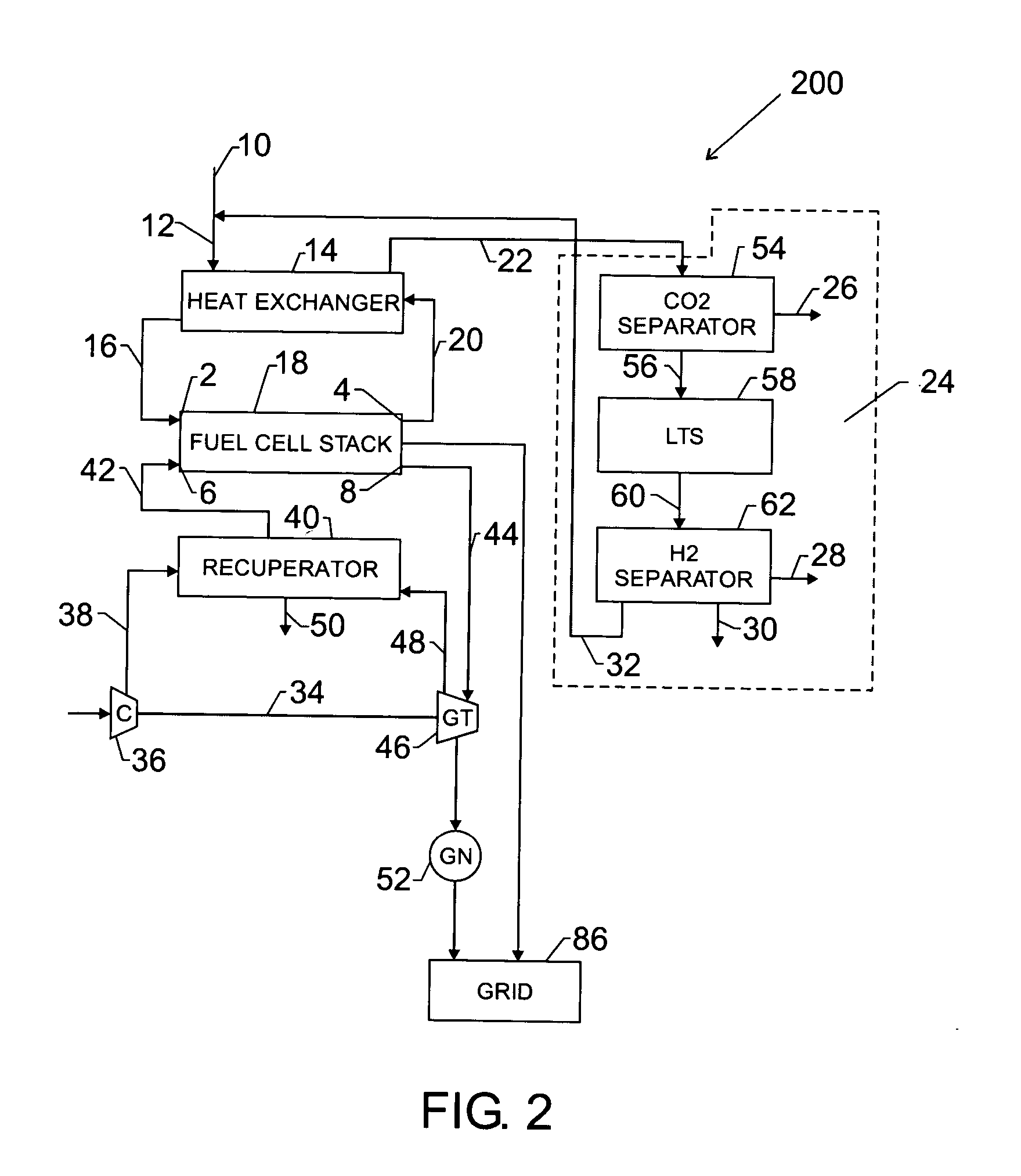
[0032] A second exemplary embodiment of the co-production system 200 is illustrated in FIG. 2. In accordance with the second embodiment, the separation unit 24 comprises a carbon dioxide separator 54, a low temperature shift (LTS) reactor 58 and a hydrogen separator 62.

[0033] The anode exhaust stream 20 is typically at a high temperature of about 600 C to about 800 C. The anode exhaust stream 20 is fed into the heat exchanger 14 to utilize the high level of heat content, thereby heating the incoming fuel stream 12. The cooled anode exhaust stream 22 is fed into the carbon dioxide separator 54. The carbon dioxide separator 54 may apply various techniques known in the art, including but not limited to pressure swing adsorption, chemical absorption and membrane separation.

[0034] Pressure swing adsorption (PSA) may be used for separation of carbon dioxide from a mixture of gases containing hydrogen. In PSA techniques, at a high partial pressure, solid molecular sieves can adsorb carbon...

fifth embodiment

[0051] In accordance with the fifth embodiment as illustrated in FIG. 5, the anode exhaust stream 20 is fed into the heat exchanger 14 to utilize the high level of heat content in the anode exhaust stream to heat the incoming fuel stream 12. The relatively cooler anode exhaust stream 22 is fed into the carbon dioxide separator 54. The carbon dioxide separator 54 may involve various techniques discussed above, including but not limited to pressure swing adsorption, chemical absorption and membrane separation.

[0052] Using one or more techniques described above, a carbon dioxide rich stream 26 and a carbon dioxide lean stream 56 are generated from the carbon dioxide separator 54. The carbon dioxide rich stream 26 may be exported for any other industrial use.

[0053] The carbon dioxide lean stream 56 comprises hydrogen, un-separated carbon dioxide, carbon monoxide, unreacted fuel and water. The carbon monoxide and water in the stream 56 may react further to produce carbon dioxide. This m...

sixth embodiment

[0058] In accordance with the sixth embodiment as shown in FIG. 6, a portion of the water stream 30 is sent to a water exchanger 72 wherein the water is heated using the heat content of the spent air 50 exiting from the recuperator 40. The heated water stream 74 is sent directly to the inlet fuel stream 10 to provide steam for the internal reforming inside the fuel assembly 18. Recycle stream 32 from the hydrogen separator 62 is sent to a catalytic combustor or a catalytic burner 82. The stream 32 comprises carbon monoxide and some amount of unreacted fuel. In order to recover energy from all fuel in the co-production system 600, in this embodiment, the recycle stream 32 is sent to a catalytic burner 82 where the recycle stream is mixed with the exhaust air stream 44 from cathode outlet 8. In the catalytic burner 82, the recycle stream 32 is combusted with the spent air stream 44 in presence of a catalyst to produce a hot gas stream 84. The hot gas stream 84 from the catalytic burne...


PUM


Abstract

A system and method for co-production of hydrogen and electrical energy. The system comprises a fuel cell assembly comprising a plurality of fuel cells. The fuel cells further comprise a cathode inlet for receiving a compressed oxidant, an anode inlet for receiving a fuel feed stream, an anode outlet in fluid communication with an anode exhaust stream and a cathode outlet in fluid communication with a cathode exhaust stream. At least a portion of the fuel feed stream reacts with the oxidant to produce electrical power. The anode exhaust stream comprises hydrogen. The co-production system further comprises a separation unit in fluid communication with the fuel cell assembly. The separation unit is configured to receive the anode exhaust stream from the fuel cell assembly to separate hydrogen from the anode exhaust stream.

Description

BACKGROUND OF THE INVENTION [0001] The present invention relates to hydrogen-based energy generation systems and more particularly to co-production of hydrogen and electrical energy utilizing integrated power generation systems. [0002] In certain hydrogen-based energy generation systems, fuel cells have been integrated with conventional gas turbines for increased power generation capacity in electrical power plants. Known fuel cells, such as, for example, solid oxide fuel cells include a plurality of solid oxide fuel cells that react a gaseous fuel, such as reformed natural gas, with air to produce electrical power and a hot gas. A compressor supplies the air for the fuel cells, which operate at elevated pressure, and produce hot gas for expansion in the turbine. Fuel cell exhaust air is combined with fuel cell exhaust fuel and the resulting heat release is converted to work in the turbine portion of the plant. Thus, electrical energy is produced by both the solid oxide fuel cell ge...

Claims


Application Information

Patent Timeline
IPC IPC(8): C01B3/50C01B3/56F02C3/20F02C3/22F02C3/36H01M8/06H01M8/12
CPCC01B3/501Y02E60/56C01B3/56C01B2203/0227C01B2203/0283C01B2203/0405C01B2203/042C01B2203/046C01B2203/0475C01B2203/0495C01B2203/84F02C3/20F02C3/22F02C3/36H01M8/04164H01M8/0612H01M8/0637H01M8/0662H01M8/0668H01M8/0687H01M2008/1293H01M2250/40Y02E60/50Y02E60/525C01B3/506
Inventor BALAN, CHELLAPPA
Owner GENERAL ELECTRIC CO
Why Eureka
Try Eureka