Fuel cell and method for manufacture thereof

a fuel cell and fuel cell technology, applied in the field of fuel cells, can solve the problems of increasing the risk of damage to the electrolyte membrane, affecting the service life of the cell, so as to prevent prolong the service life, and prevent the effect of local deformation and concentration

Inactive Publication Date: 2005-06-09
MITSUBISHI ELECTRIC CORP
View PDF1 Cites 24 Cited by
  • Summary
  • Abstract
  • Description
  • Claims
  • Application Information

AI Technical Summary

Benefits of technology

[0014] An object of the present invention is to provide a fuel cell having a sealing portion for an electrode substrate reliably forming a gas seal and supporting a solid polymer electrolyte membrane uniformly while ensuring a satisfactory electrochemically active region, and to provide a method for the manufacture thereof.
[0016] In a fuel cell according to the present invention, because electrode substrates are included to support the solid polymer electrolyte membrane so as to prevent local deformation and concentrations of stress while reliably forming a gas seal, damage to the solid polymer electrolyte membrane can be prevented. Because the gas seal form is reliably, service life is extended by reducing undervoltage in the fuel cell, and safety is improved by preventing combustion of fuel gas and abnormal overheating of the fuel cell.

Problems solved by technology

However, because the solid polymer electrolyte membrane contracts when it dries out and swells when it absorbs moisture, stresses act on the solid polymer electrolyte membrane with repeated running and stopping.
Because stresses act on the solid polymer electrolyte membrane in this manner, there has been a risk that the solid polymer electrolyte membrane may be damaged unless the solid polymer electrolyte membrane is reliably supported.
In addition, damage to the electrolyte membrane often occurs in portions of the electrolyte membrane positioned at a boundary between a power generating portion and a gas seal portion.
In particular, when the electrolyte membrane in this portion is exposed to wet reactant gas, damage to the electrolyte membrane occurs more easily due to stresses accompanying contraction, etc., of the electrolyte membrane.
In other words, the electrolyte membrane is more likely to be wetted by the reaction product water in the power generating portion, and on the other hand, the electrolyte membrane is more likely to dry out in the gas seal portion.
Thus, if the electrolyte membrane cracks, or pinholes form in this manner, gas may leak through these between the first and second electrodes, reducing the output voltage of the fuel cell.
In addition, damage to the electrolyte membrane may spread if operation is continued without intervention because the rate of gas leakage will increase, react on a catalyst, and partially increase the temperature.
(For example, see Japanese Patent Laid-Open No. 2000-260443) However, stresses are concentrated at a boundary portion between the current-carrying portion of the solid polymer electrolyte membrane and the non-current-carrying portion reinforced by the reinforcing material, and there has been a risk that cracking may occur along that boundary portion.
However, one problem has been that many communicating pores remain in a resin that has been hardened by performing impregnation then removing the solvent, making it difficult to seal off the fuel and the oxidizer gas.
In addition, because the solid polymer electrolyte membrane is stacked after the electrode substrate has been compacted, another problem has been that it is difficult to seal the gases off completely since the surface of the solid polymer electrolyte membrane is merely in contact with and not bonded to the surface of the compacted portion of the electrode substrate.
For that reason, another problem has been that it is difficult to inject the liquid compound only in the sealing region of the electrodes with complete vacuum impregnation, and it also enters the electrochemically active region, reducing the area of the active region.

Method used


Image

  • Fuel cell and method for manufacture thereof
  • Fuel cell and method for manufacture thereof
  • Fuel cell and method for manufacture thereof

Examples


embodiment 1

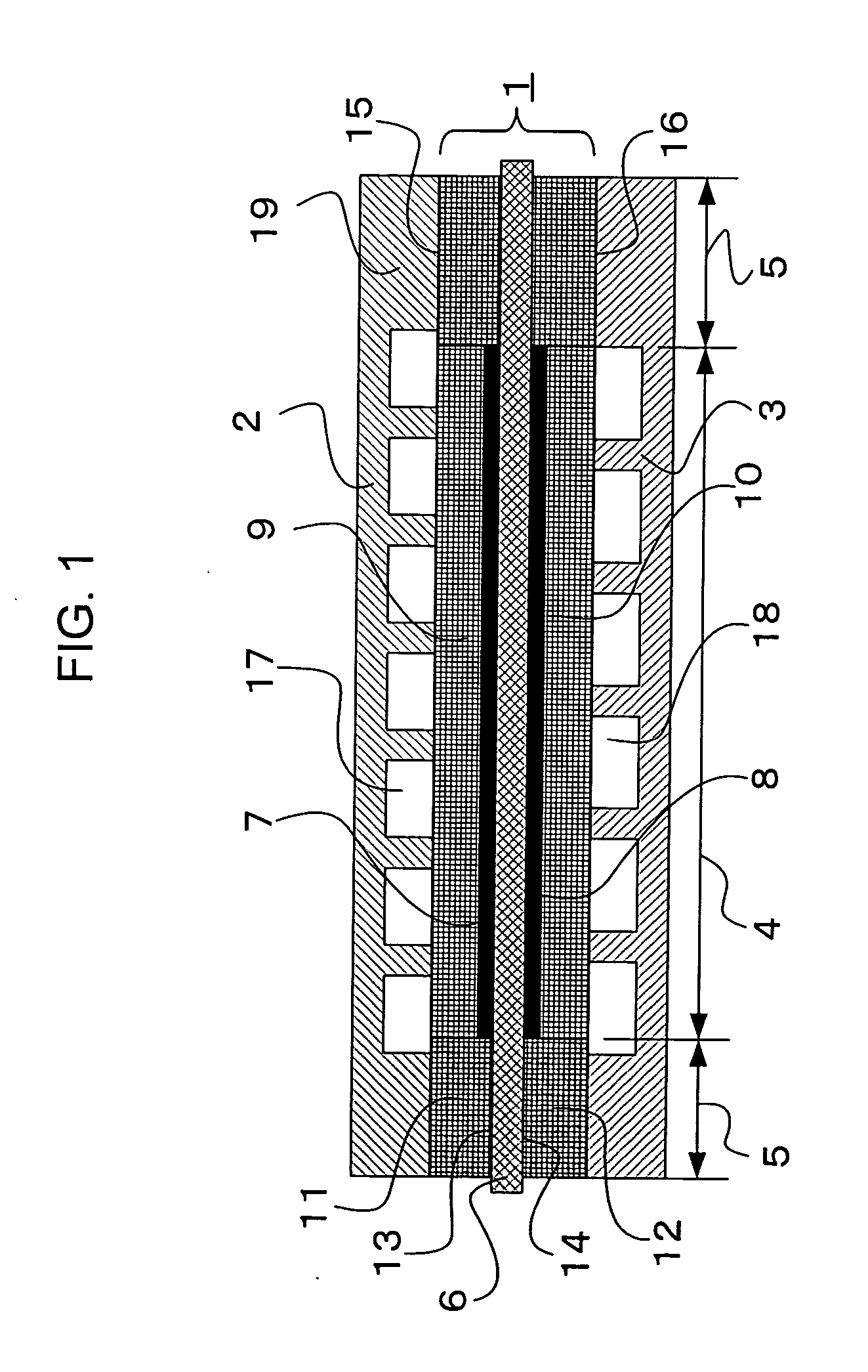
[0041]FIG. 1 is a cross-sectional schematic diagram of a solid polymer fuel cell according to Embodiment 1 of the present invention.

[0042] A single cell of this solid polymer fuel cell (hereinafter “fuel cell”) has: a membrane electrode composite body 1; and an electrically-conductive oxidizer separator plate 2 and an electrically-conductive fuel separator plate 3, together holding the membrane electrode composite body 1 from two sides. The membrane electrode composite body 1 has: a power generating portion 4 for generating electric power by ionizing into protons hydrogen functioning as a fuel, conducting the protons as ions, and oxidizing the protons with oxygen functioning as an oxidizer; and a sealing portion 5 surrounding a perimeter of the power generating portion 4 to seal off the fuel and the oxidizer.

[0043] The membrane electrode composite body 1 has: a proton-conductive solid polymer electrolyte membrane (hereinafter “electrolyte membrane”) 6 spreading over an entire surf...

##ventive example 1

INVENTIVE EXAMPLE 1

[0078] Next, Inventive Example 1 of the fuel cell according to the present invention will be explained. The construction of single cells in the fuel cells of Inventive Example 1 is similar to that in FIG. 1.

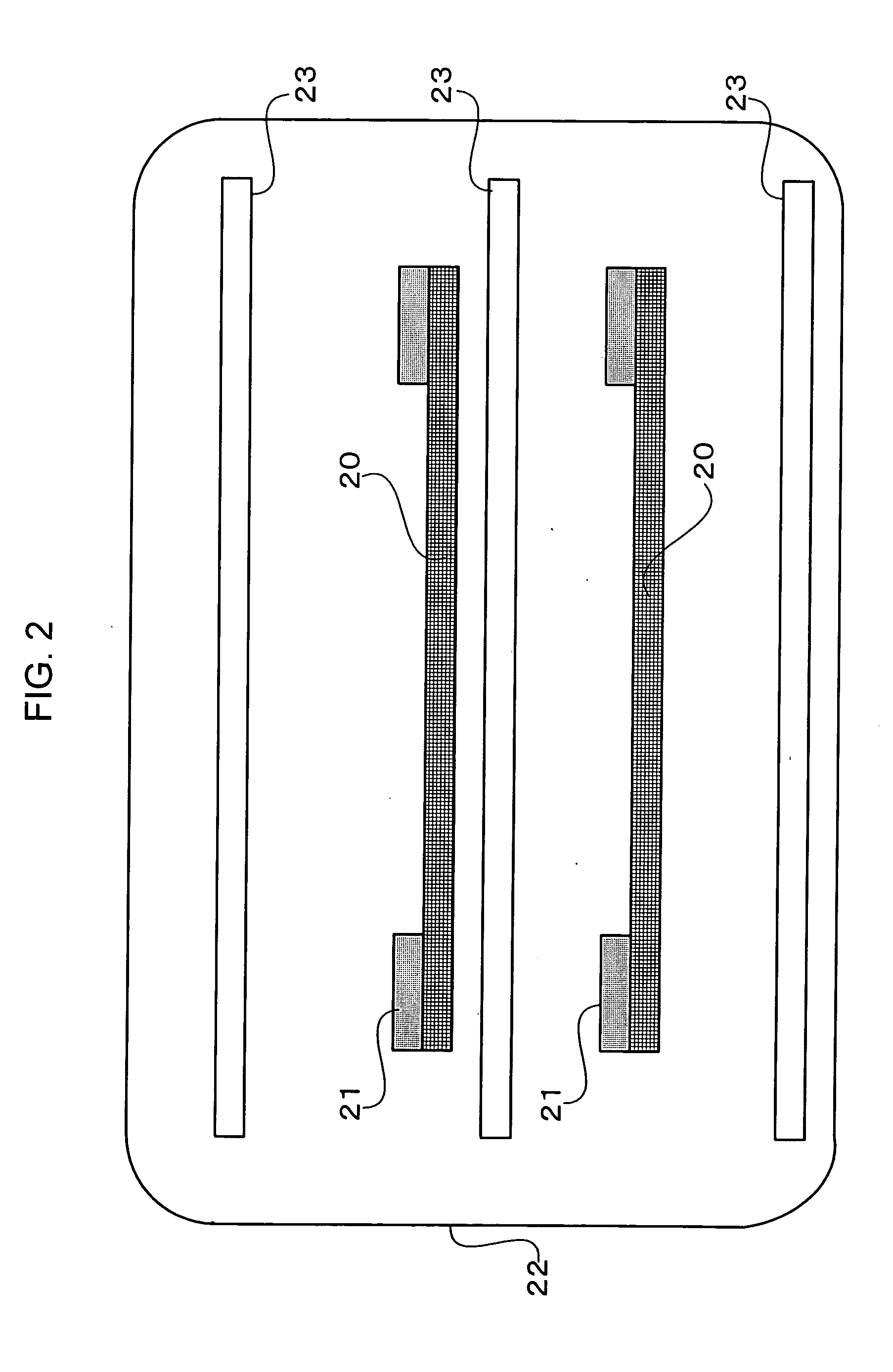
[0079] First, square electrode substrate plate 20 having 90 mm to a side were prepared from a carbon paper having a thickness of 300 μm (TGP-H-90 manufactured by Toray Industries, Inc.). The porosity of this carbon paper was approximately 78 percent. Frame-shaped resin sheets 21 having a square external shape having 90 mm to a side and having a square aperture having 54 mm to a side opened in a central portion were cut out of a resin film having a thickness of 257 μm. As shown in FIG. 2, an oxidizer electrode substrate 9 and a fuel electrode substrate 10 in which an oxidizer-sealing support portion 11 and a fuel-sealing support portion 12 were disposed were produced by stacking these resin sheets 21 with the electrode substrate plates 20, setting them between ...

##ventive example 2

INVENTIVE EXAMPLE 2

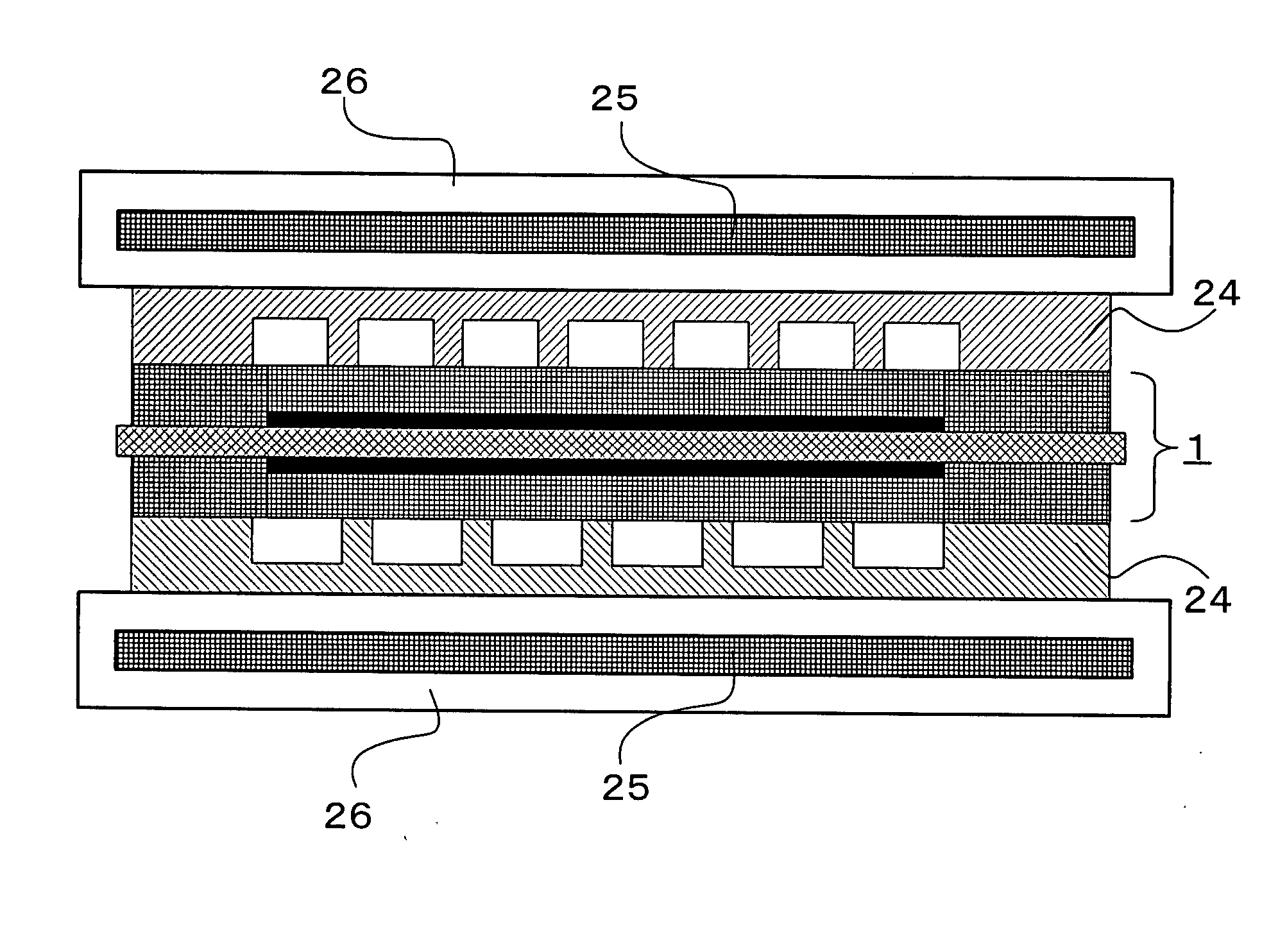
[0102]FIG. 7 is a cross section of a single cell of a fuel cell according to Inventive Example 2 of the present invention. In this single cell, a membrane electrode composite body 1 was formed in a similar manner to that of Inventive Example 1. This membrane electrode composite body 1 was subsequently sandwiched between an electrically-conductive oxidizer separator plate 2 and an electrically-conductive fuel separator plate 3 in which gas channels were disposed to form a single cell stacked body. Hot-pressing was applied to this single cell stacked body for two minutes at a temperature of 120 degrees Celsius and a pressure of 49 N / cm2. By this process, thermoplastic resin filling an oxidizer-sealing support portion 11 and a fuel-sealing support portion 12 was re-softened, bonding the electrically-conductive oxidizer separator plate 2 and the electrically-conductive fuel separator plate 3 with the membrane electrode composite body 1 to produce the single cell.

[010...


PUM

PropertyMeasurementUnit
widthaaaaaaaaaa
volume percentaaaaaaaaaa
widthaaaaaaaaaa

Abstract

A fuel cell includes a membrane electrode composite body in which a cathode catalyst layer and an anode catalyst layer are joined to central portions of two surfaces of a solid polymer electrolyte membrane and further held from two sides between a fuel electrode substrate having a surface area that is larger than that of the cathode catalyst layer and an oxidizer electrode substrate having a surface area that is larger than that of the anode catalyst layer, wherein: pores of a fuel-sealing support portion surrounding the cathode catalyst layer in the fuel electrode substrate are partially or wholly filled with a resin; pores of an oxidizer-sealing support portion surrounding the anode catalyst layer in the oxidizer electrode substrate are partially or wholly filled with the resin; and the fuel-sealing support portion and the oxidizer-sealing support portion are bonded to the solid polymer electrolyte membrane by the resin.

Description

BACKGROUND OF THE INVENTION [0001] 1. Field of the Invention [0002] The present invention relates to a fuel cell making use of an electrochemical reaction to generate electric power, and to a method for the manufacture thereof. [0003] 2. Description of the Related Art [0004] Fuel cells are devices for converting chemical energy directly into electric energy by interposing an electrolyte membrane between a pair of opposing first and second electrodes, supplying a fuel to the first electrode and an oxidizer to the second electrode, and permitting the fuel and the oxidizer to react inside the fuel cell electrochemically. Among such fuel cells, solid polymer fuel cells can achieve high output characteristics because they use solid polymer electrolyte membranes having proton conductivity for the electrolyte membrane. [0005] The electrochemical reactions in these solid polymer fuel cells are sustained by continuously supplying a reactant gas. Ion conductivity of the electrolyte membrane, ...

Claims


Application Information

Patent Timeline
Patent Type & Authority Applications(United States)
IPC IPC(8): H01M2/08H01M4/86H01M4/88H01M8/00H01M8/02H01M8/10H01M8/24
CPCH01M8/0258H01M8/0267Y02E60/521H01M8/1002H01M2008/1095H01M8/0273H01M8/0263H01M8/1007H01M8/2483Y02E60/50Y02P70/50H01M8/0271
Inventor HIROI, OSAMUFUKUMOTO, HISATOSHIYOSHIOKA, SHOJIMAEDA, HIDEOURUSHIBATA, HIROAKIKURIKI, HIRONORINISHIMURA, TAKASHI
Owner MITSUBISHI ELECTRIC CORP
Why Eureka
Try Eureka