Method for determining and correcting vision

a technology of optical aberration and measurement method, applied in the field of optical aberration measurement and correction, can solve the problems of affecting the system's performance, deformation or distortion of reflected light waves exiting the eye, and the conventional method of determining refractive errors in the eye is substantially less accurate than the techniques now available, and achieves the effect of simple and inexpensive design

Inactive Publication Date: 2005-06-09
FREY RUDOLPH W +4
View PDF99 Cites 192 Cited by
  • Summary
  • Abstract
  • Description
  • Claims
  • Application Information

AI Technical Summary

Benefits of technology

[0016] In general, an embodiment of the present invention provides a method and system for objectively measuring aberrations of optical systems by wavefront analysis and use such measurement to generate an optical correction. Another embodiment further provides for the objective measurement of ocular aberrations having a dynamic range that can cope with large amounts of such aberrations so as to be useful in practical applications. Still another embodiment of the present invention provides a method and system for objectively measuring ocular aberrations using a wavefront analyzer of simple and inexpensive design.
[0017] One embodiment of the present invention provides an apparatus and method for making objective and detailed measurements of aberrations present in human eyes. Aberrations measured by the apparatus include “higher order” phenomena, such as spherical aberration and coma, in addition to the traditional myopia / hyperopia and astigmatism. Once the apparatus obtains data representing aberration information, this data is transferred to a treatment system which may employ a small diameter treatment laser beam, may employ a computer controlled laser pulse placement, and may employ an active eye-tracking module. These treatment system features permit corrective laser surgery to address, and ideally to eliminate, the aberrations measured by the apparatus. Another means of correction may be employed, such as an embodiment of the present of the present invention which improves visual performance of treated eyes beyond the level obtained by current refractive procedures.

Problems solved by technology

In either case, aberrations in the optical system can affect the system's performance.
However, an eye typically has aberrations that cause deformation or distortion of reflected light waves exiting the eye.
Thus, conventional methodology for determining refractive errors in the eye is substantially less accurate than the techniques now available for correcting the ocular aberrations.
However, a small uncertainty or error in the location of the beam's point of incidence on the cornea exists due to the curved corneal surface.
A major limitation to the approach described by Penney '791 is that a separate measurement of corneal topography is desired to perform the Snell's Law analysis of needed refraction change.
This adds significantly to the time and cost of a complete and desirable diagnostic evaluation.
In addition, any error in the spatial orientation of a topography map with respect to a refraction map will degrade the accuracy of the needed correction profile.
Yet another limitation to known approaches such as described in Penney '791, by way of example, is that test points on the corneal surface are examined sequentially.
Eye motion during the examination, either voluntary or involuntary, could introduce substantial errors in the refraction measurement.
However, this approach may still allow substantial undetected eye movement error between such iris reference points.
However, when the perfect eye receives a collimated beam of light, the best possible image on the retina is a diffraction limited spot.
Providing a corrective or lens combination, as well as setting up for their use becomes cumbersome, time consuming, and at an additional expense.
However, the system disclosed by Liang et al. is effective only for eyes having fairly good vision.
Eyes that exhibit considerable myopia (near-sightedness) would cause the focus spots to overlap on the CCD, thereby making local slope determination practically impossible for eyes having this condition.
Similarly, eyes that exhibit considerable hyperopia (farsightedness) deflect the focus spots such that they do not impinge on the CCD thereby again making local slope determination practically impossible for eyes having this condition.

Method used


Image

  • Method for determining and correcting vision
  • Method for determining and correcting vision
  • Method for determining and correcting vision

Examples


Embodiment Construction

[0075] The present invention will now be described more fully hereinafter with reference to the accompanying drawings, in which embodiments of the present invention are shown by way of illustration and example. This invention may, however, be embodied in many forms and should not be construed as limited to the embodiments set forth herein. Rather, these embodiments are provided so that this disclosure will be thorough and complete, and will fully convey the scope of the invention to those skilled in the art. Like numbers refer to like elements throughout.

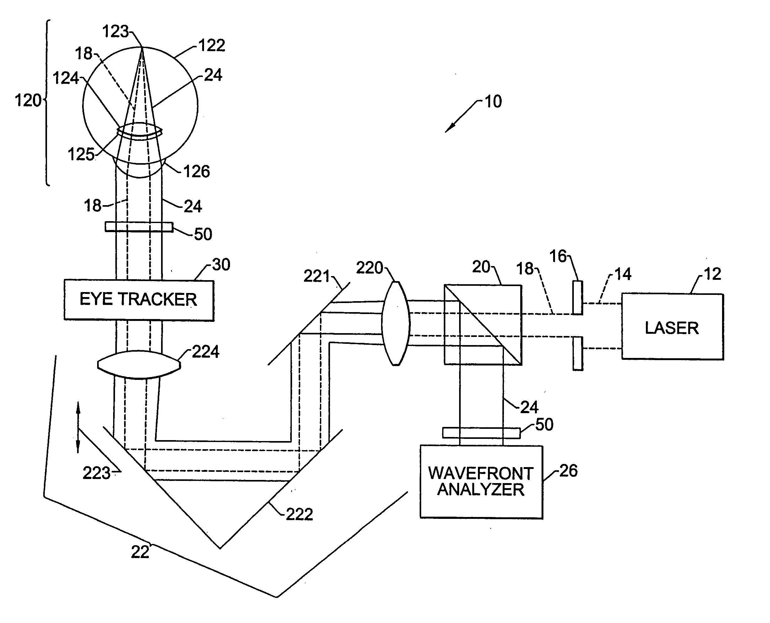
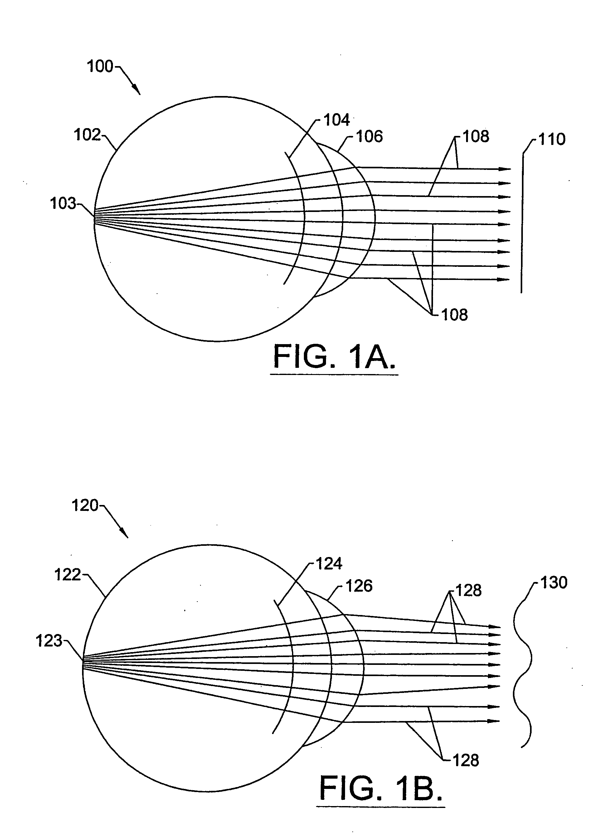
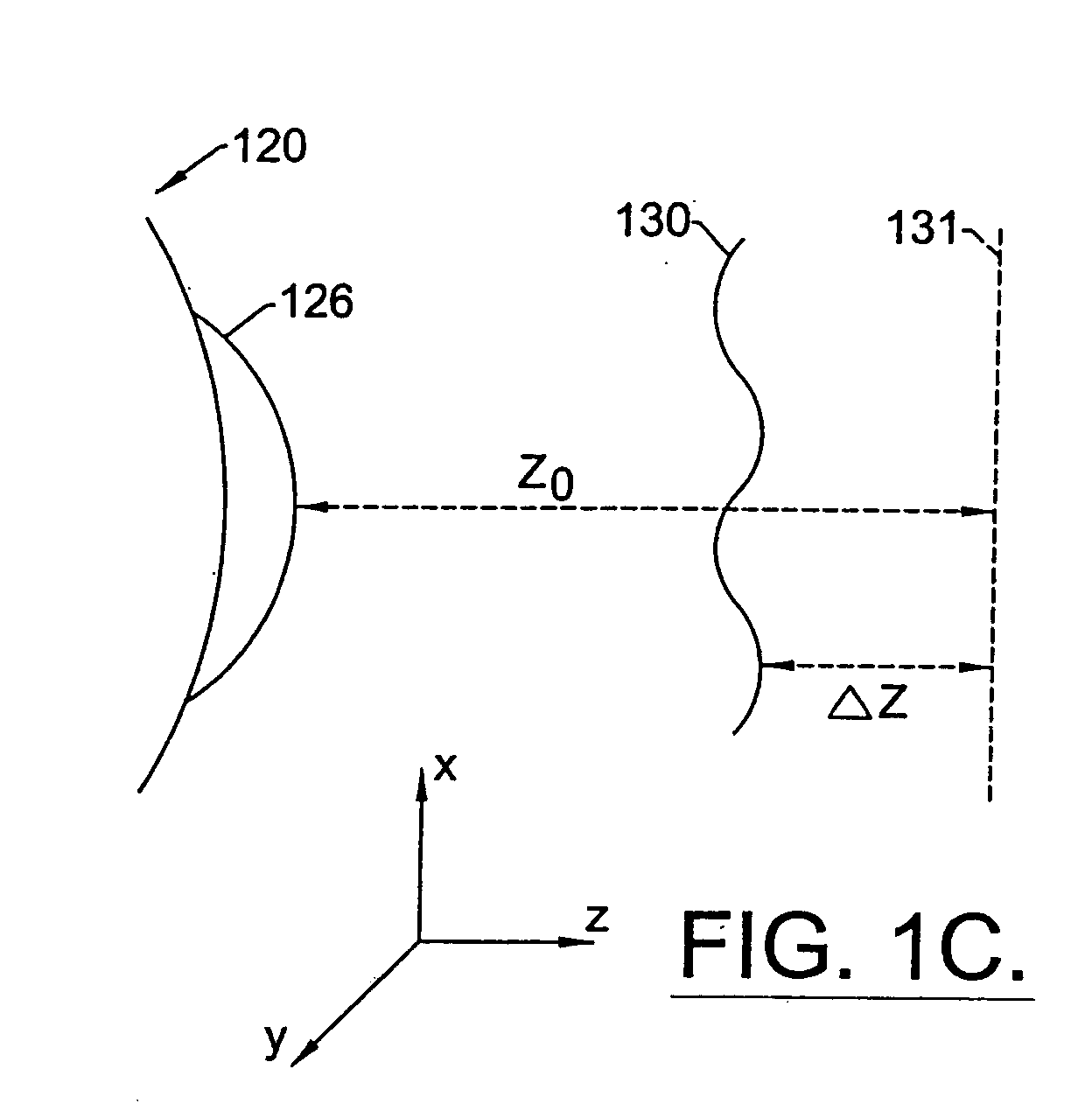
[0076] By way of illustrative example, the present invention will be described with respect to diagnosing and correcting a human eye. However, it is to be understood that the teachings of the present invention are applicable to any optical system having a real image focus that can be, or can be adapted to diffusely reflect a focused spot of radiation from a rear portion of the optical system back through the optical system as a wav...


PUM


Abstract

A method for enhancing vision of an eye includes a laser delivery system having a laser beam for ablating corneal material from the cornea of the eye. Measurements are made to determine an optical path difference between a plane wave and a wavefront emanating from the retina of the eye for a location at a surface of the cornea. An optical correction is provided to the laser delivery system for the location based on the optical path difference and refractive indices of media through which the wavefront passes. The optical correction includes dividing the optical path difference by a difference between an index of refraction of corneal material and an index of refraction of air. The laser beam is directed to the location on the surface of the cornea and corneal material ablated at the location in response to the optical correction to cause the wavefront to approximate the shape of the plane wave at that location.

Description

CROSS REFERENCE TO RELATED APPLICATIONS [0001] This application is a continuation of application Ser. No. 09 / 745,192, filed Dec. 21, 2000, currently co-pending, for “Method for Determining and Correcting Vision,” which itself is a continuation of application Ser. No. 09 / 566,668 filed May 8, 2000 for “Apparatus and Method for Objective Measurement and Correction of Optical Systems,” which itself is a continuation-in-part of application Ser. No. 09 / 324,179 filed May 20, 1998 for “Objective Measurement and Correction of Optical Systems Using Wavefront Analysis,” which itself is a continuation of application Ser. No. 08 / 756,272 filed Nov. 25, 1996 for “Objective Measurement and Correction of Optical Systems Using Wavefront Analysis,” now abandoned, all of which are commonly owned and have the disclosures incorporated by reference.FIELD OF THE INVENTION [0002] The invention relates generally to optical aberration measurement and correction, and more particularly to an objective measureme...

Claims


Application Information

Patent Timeline
Patent Type & Authority Applications(United States)
IPC IPC(8): A61B3/103A61B3/107A61B3/15A61F9/008A61F9/01
CPCA61F9/00806A61F2009/00846A61F2009/0088A61F2009/00872A61F2009/00848
Inventor FREY, RUDOLPH W.BURKHALTER, JAMES H.ZEPKIN, NEILPOPPELIERS, EDWARDCAMPIN, JOHN ALFRED
Owner FREY RUDOLPH W
Why Eureka
Try Eureka