Liquid metal ion gun

a metal ion gun and ion source technology, applied in the field of liquid metal ion sources, can solve the problems of increasing the distance between an emitter and a beam limiting aperture, the difficulty of recovering when the emission becomes unstable, and the inability to consider the difficulty of returning the emission unstable, etc., to prolong the life of increase the distance between the emitter and the beam limiting aperture, and high reproducibility

Inactive Publication Date: 2005-06-16
HITACHI HIGH-TECH CORP
View PDF6 Cites 13 Cited by
  • Summary
  • Abstract
  • Description
  • Claims
  • Application Information

AI Technical Summary

Benefits of technology

[0021] In view of the above-described problems, objects of the present invention are described blow. That is, an object is to stabilize emission for a long time even if the distance between an emitter and a beam limiting aperture is small. In addition, an object is to extend the life time of a beam limiting aperture even if receiving sputtering by beam emission. Further, an object is, when the emission of the liquid metal ion source becomes unstable, to recover the emission in a stable state at high reproducibility to use a liquid metal ion source for a long time to lengthen the life time thereof. Furthermore, an object is to provide a stable liquid metal ion gun not requiring beam adjustment of a focused ion beam system.
[0022] According to a first aspect of the invention, there is provided a liquid metal ion gun comprising: a liquid metal ion source having a liquid metal ion element made of a first metal substrate, a reservoir formed by as second metal substrate for holding the liquid metal ion element, and an emitter formed by the second metal substrate; and a beam limiting aperture formed by a third metal substrate, the beam limiting aperture having an aperture for limiting emission of an ion beam extracted from the liquid metal ion source, wherein the third metal substrate is formed by a material including the metal substrates constituting the first metal substrate and the second metal substrate, respectively. By using this liquid metal ion gun, it is possible to decrease the number of factors of contaminating the emitter. The third metal substrate constituting the beam limiting aperture may be constituted only by the first metal substrate and the second metal substrate. Also, the ion gun may be provided with an acceleration mechanism.
[0023] Further, in a liquid metal ion gun comprising: a liquid metal ion source having a liquid metal ion element made of a first metal substrate, a reservoir formed by as second metal substrate for holding the liquid metal ion element, and an emitter formed by the second metal substrate; and a beam limiting aperture formed by a third metal substrate, the beam limiting aperture having an aperture for limiting emission of an ion beam extracted from the liquid metal ion source, it is preferable that the beam limiting aperture is formed by a material including the second metal substrate, and a supply source of the first metal substrate is arranged in at least a part of a region to which the ion beam is substantially emitted. By this features, it is possible to easily reduce the above contamination factors.
[0024] According to the invention, in fabrication by a large current beam of a focused ion beam apparatus or the like provided with a liquid metal ion source, it is possible to perform the fabrication with no damage due to the ion emission around the fabrication. According to the liquid metal ion gun of the invention, in a liquid metal ion source having a purpose of using for several hundreds hours or more, it is superior in point of stably maintaining emission for a long time, and in point of securely recovering unstable emission into a stable state, that is, superior in easiness and reproducibility of recovery of emission stability.

Problems solved by technology

Even if using the above technique, it is difficult to return the emission which becomes unstable as a result of stably maintaining the emission for a long time to a stable state in a liquid metal ion source preferable to be used for hundreds of hours or more.
That is, the difficulty of recovery when emission becomes unstable has not been considered.
Moreover, when desiring to realize a focused ion beam system for a high-current and high-angular-intensity processing beam, it is not preferable to greatly increase the distance between an emitter and a beam limiting aperture.

Method used


Image

  • Liquid metal ion gun
  • Liquid metal ion gun
  • Liquid metal ion gun

Examples


Embodiment Construction

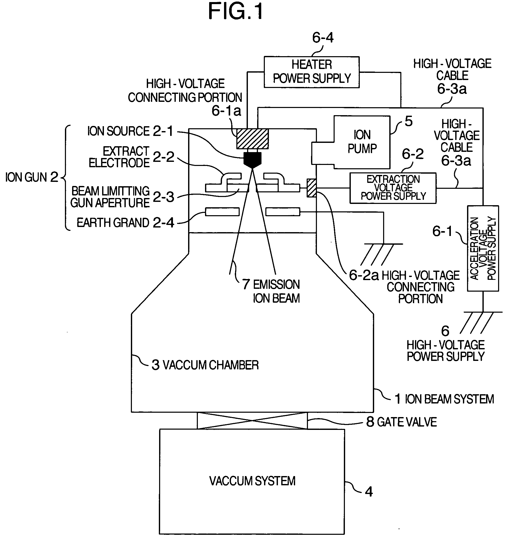
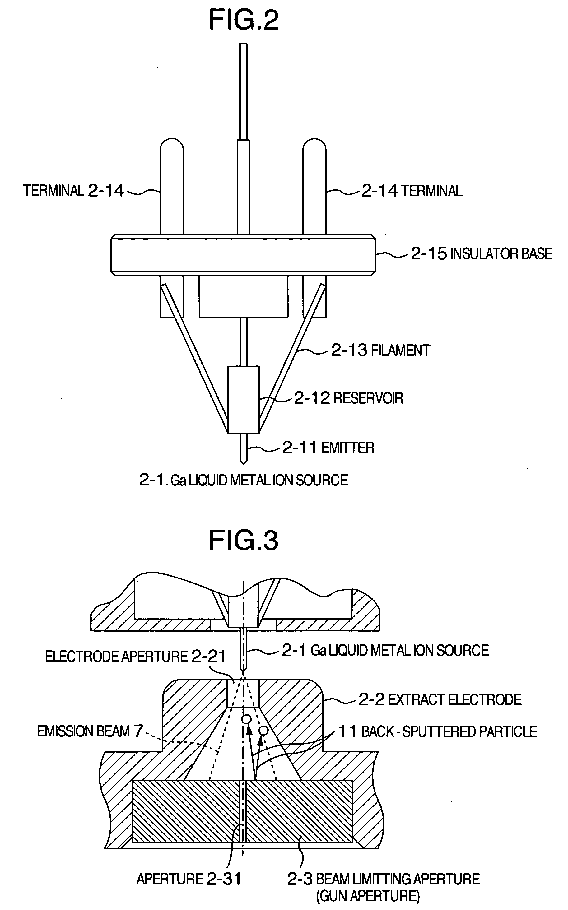
[0033] A liquid metal ion gun according to an embodiment of the present invention is described below by referring to the accompanying drawings. A liquid ion gun of the present invention relates to a liquid metal ion gun on which a liquid metal ion source and a beam limiting aperture for receiving emission of ions emitted from the liquid metal ion source are mounted.

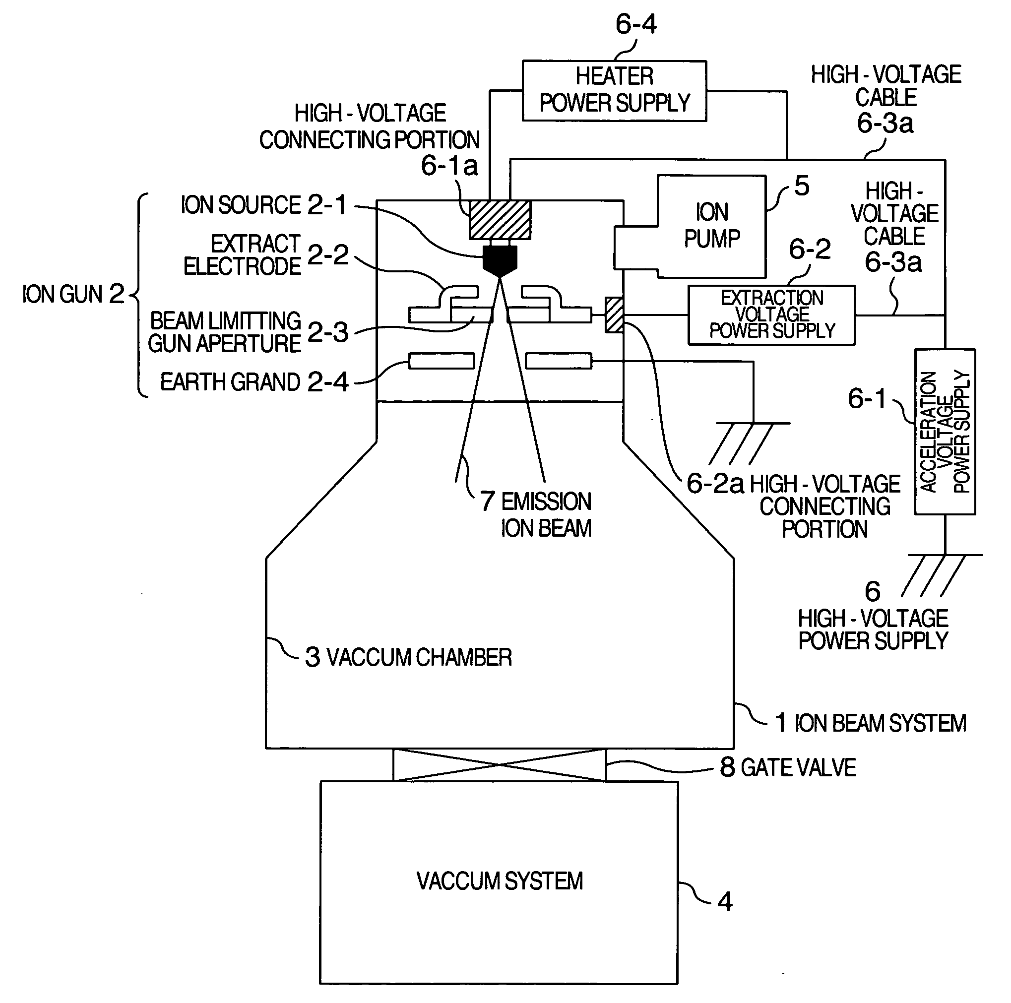
[0034] Firstly, the whole configuration of an apparatus on which an ion gun according to an embodiment of the present invention is mounted is described below by referring to FIG. 1. FIG. 1 is a schematic configuration view of an ion beam system using a Ga liquid metal ion gun according to an embodiment of the present invention. In FIG. 1, reference numeral 1 denotes an ion beam system, and reference numeral 2 denotes an ion gun wherein reference numeral 2-1 denotes an ion source, reference numeral 2-2 denotes an extractor electrode, reference numeral 2-3 denotes a beam limiting aperture, reference numeral 2-4 denotes ear...


PUM


Abstract

An emitter of a Ga liquid metal ion source is constituted to include W12 of a base material and Ga9 of an ion source element covering a surface as construction materials. By making back-sputtered particles become elements (W and Ga) of the Ga liquid metal ion sour source, if back-sputtered particles attach to the Ga liquid metal ion source, contamination which may change physical characteristics of Ga9 does not occur. A W aperture is used as a beam limiting (GUN) aperture to place Ga of approx. 25 mg (of melting point of 30° C.) on a surface of a portion included in a beam emission region (Ga store). When emitting ions to the beam limiting (GUN) aperture, Ga in the emission region melts and diffuses on a surface of the beam emission region of the W aperture.

Description

BACKGROUND OF THE INVENTION [0001] 1. Field of the Invention [0002] The present invention relates to a liquid metal ion source (LMIS), and more particularly to an art of making the ion emission of a Ga liquid metal ion source stable and long life time. [0003] 2. Description of the Prior Art [0004] A liquid metal ion gun includes a vacuum chamber in which a liquid metal ion source is set, and the liquid metal ion source electrically insulated from the vacuum chamber. A high voltage cable capable of supplying current between both terminals of the liquid metal ion source is connected to the liquid metal ion gun and thereby, it is possible to supply a high voltage to the liquid metal ion source so as to apply the high voltage to the liquid metal ion source appropriately and to heat the liquid metal ion source by turning on electricity. [0005] It is possible to adjust an ion emission quantity (emission current) by voltage between the liquid metal ion source and an extract electrode. The ...

Claims


Application Information

Patent Timeline
Patent Type & Authority Applications(United States)
IPC IPC(8): H01J27/26G21G5/00H01J27/00H01J27/02H01J37/08
CPCH01J27/02H01J2237/0805H01J37/08H01J27/22
Inventor KAGA, HIROYASUMADOKORO, YUICHIIZAWA, SHIGERUISHITANI, TOHRUUMEMURA, KAORU
Owner HITACHI HIGH-TECH CORP
Why Eureka
Try Eureka