Method and apparatus for three-dimensional spectrally encoded imaging

a three-dimensional spectrally encoded and imaging technology, applied in the field of optical imaging, can solve the problems of reducing the accuracy of the image, so as to improve the accuracy and accuracy of the image. , the three-dimensional field of view of the device is limited to less than a few millimeters, and the size of the device is increased. cost, complexity,

Active Publication Date: 2005-06-16
THE GENERAL HOSPITAL CORP
View PDF99 Cites 163 Cited by
  • Summary
  • Abstract
  • Description
  • Claims
  • Application Information

AI Technical Summary

Benefits of technology

[0010] In one embodiment, a surface profile of an object is measured by utilizing the technique of the present invention in conjunction with a probe of the type described in published PCT application number WO 02 / 038040 A2 (now pending in the U.S. Patent and Trademark Office as application Ser. No. 09 / 709,162 filed Nov. 10, 2000) said application being assigned to the assignee of the present invention. The techniques of the present invention can thus be used in conjunction with techniques for performing a miniature endoscopy with a high number of resolvable points as described in the aforementioned U.S. application Ser. No. 09 / 709,162. The aforementioned U.S. application Ser. No. 09 / 709,162 describes a technique in which a broadband light source and a diffraction grating are used to spectrally encode reflectance across a transverse line within a sample and a two-dimensional image is formed by scanning this spectrally encoded line. Since this method only requires a single optical fiber, it is capable of enabling two-dimensional imaging through a small diameter, flexible probe. By utilizing the techniques of the present invention, a three-dimensional spectrally-encoded image can be provided. In three-dimensional spectrally-encoded imaging, the transverse location of the image is encoded by wavelength and the axial or depth coordinate of each point is encoded by phase.

Problems solved by technology

Depth resolved imaging with a large, three-dimensional field of view is more challenging when utilizing small diameter flexible imaging probes such as borescopes, laparoscopes, and endoscopes.
The three-dimensional field of view for these devices, however, is limited to less than a few millimeters due to the small objective lens clear aperture and low f-number required for high-resolution optical sectioning.
These methods all require additional hardware for the probe, increasing the size, cost, and complexity of these devices.

Method used


Image

  • Method and apparatus for three-dimensional spectrally encoded imaging
  • Method and apparatus for three-dimensional spectrally encoded imaging
  • Method and apparatus for three-dimensional spectrally encoded imaging

Examples


Embodiment Construction

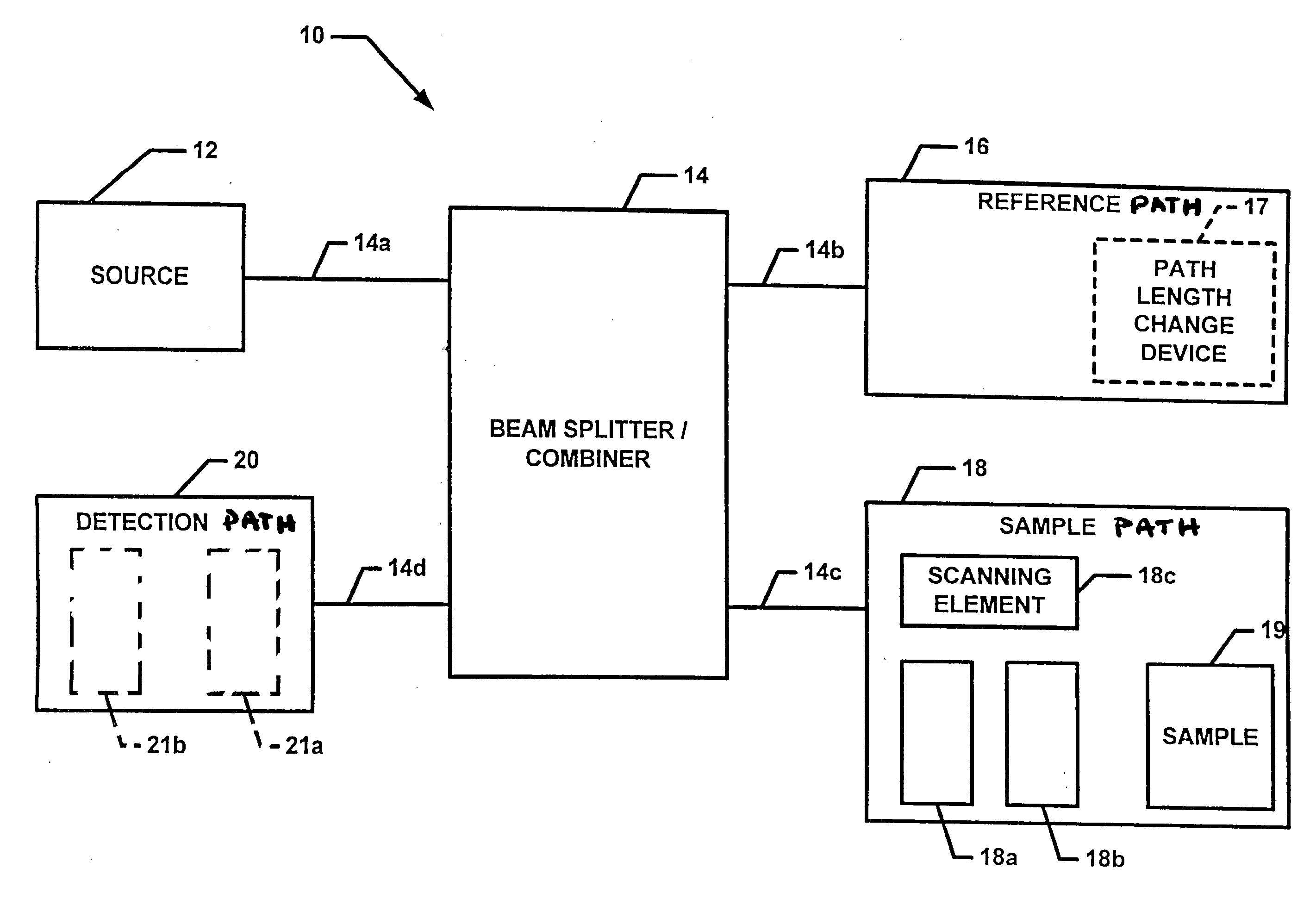
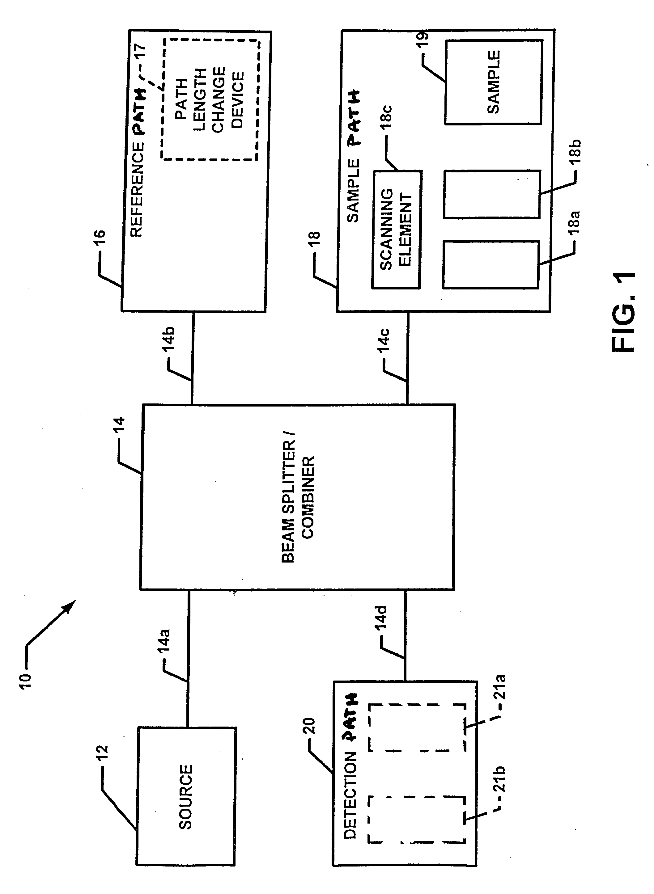
[0027] Referring now to FIG. 1, a three-dimensional spectrally encoded imaging system 10 includes a source 12 coupled to a beam splitter 14 at first port 14a. It should be appreciated that beam splitter 14 may be implement using any techniques now known or later discovered. For example, splitter 14 may be provided as a fiber optic beam splitter, a free space splitter or a glass plate splitter.

[0028] The system 10 includes a reference path 16 coupled to a second port 14b of the beam splitter 14 and a sample path 18 coupled to a third port 14c of the beam splitter 14. The reference path 16 includes a path-length change device 17. Path-length change device 17 is adapted to change a propagation path length of light propagating in the reference path 16. The device 17 allows the optical path length of the reference arm 17 to be changed in a controlled and known manner. In some embodiments, device 17 may be provided such that it can introduce a change in the group delay of optical signals...


PUM


Abstract

A method and apparatus for obtaining three-dimensional surface measurements using phase-sensitive spectrally encoded imaging is described. Both transverse and depth information is transmitted through a single-mode optical fiber, allowing this technique to be incorporated into a miniature probe.

Description

CROSS-REFERENCE TO RELATED APPLICATIONS [0001] This application claims the benefit under 35 U.S.C. §119(e) of Provisional Application No. 60 / 525,684 filed Nov. 28, 2003.STATEMENTS REGARDING FEDERALLY SPONSORED RESEARCH [0002] Not applicable. FIELD OF THE INVENTION [0003] This invention relates generally optical imaging and more particularly to a method and apparatus for performing three-dimensional surface measurements. BACKGROUND OF THE INVENTION [0004] As is known in the art, optical techniques for surface profilometry are commonly performed using interferometric measurements. Analyzing the interference fringe pattern formed by overlap of a reflected wave from an optically smooth surface with a reference wave, enables surface profile measurements with high accuracy. Projecting an interference fringe pattern on an object surface is effective for probing rough surfaces. High-resolution, point-by-point measurements of rough surfaces have been demonstrated using a long coherence lengt...

Claims


Application Information

Patent Timeline
Patent Type & Authority Applications(United States)
IPC IPC(8): A61B1/04A61B1/07A61B5/107G01B9/02G01B11/24G01B11/25G01B11/30
CPCA61B1/042G01B11/2509G01B11/2441A61B5/1077G01B9/02044G01B9/02027
Inventor YELIN, DVIRBOUMA, BRETT E.IFTIMIA, NICUSORTEARNEY, GUILLERMO J.
Owner THE GENERAL HOSPITAL CORP
Why Eureka
Try Eureka