Blazed holographic grating, method for producing the same and replica grating

Inactive Publication Date: 2005-06-16
SHIMADZU CORP
View PDF3 Cites 39 Cited by
  • Summary
  • Abstract
  • Description
  • Claims
  • Application Information

AI Technical Summary

Benefits of technology

[0010] The invention has been worked out to solve the foregoing problems. An object of the invention is to provide a blazed holographic grating which comprises a sawtooth grating groove the vertex of which has an assured sharpness to attain a high diffraction efficiency and pro

Problems solved by technology

This also causes the worsening of crosswise meandering of the grating groove.
The fact that the photoresist has a roughened surface means that the height of the photoresist layer is not uniform.
When the initial height of the resist pattern is not uniform, it is absolutely impossible to terminate the etching just when the entire resist pattern disappears.
Therefore, the vertex of the groove which has been sharpen

Method used


Image

  • Blazed holographic grating, method for producing the same and replica grating
  • Blazed holographic grating, method for producing the same and replica grating
  • Blazed holographic grating, method for producing the same and replica grating

Examples


Embodiment Construction

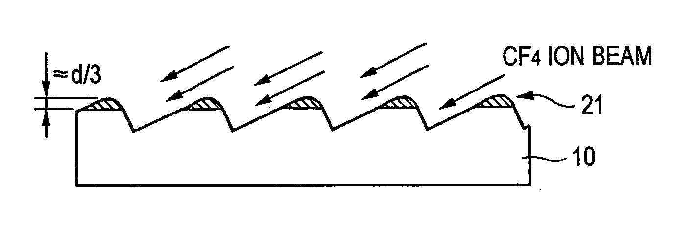
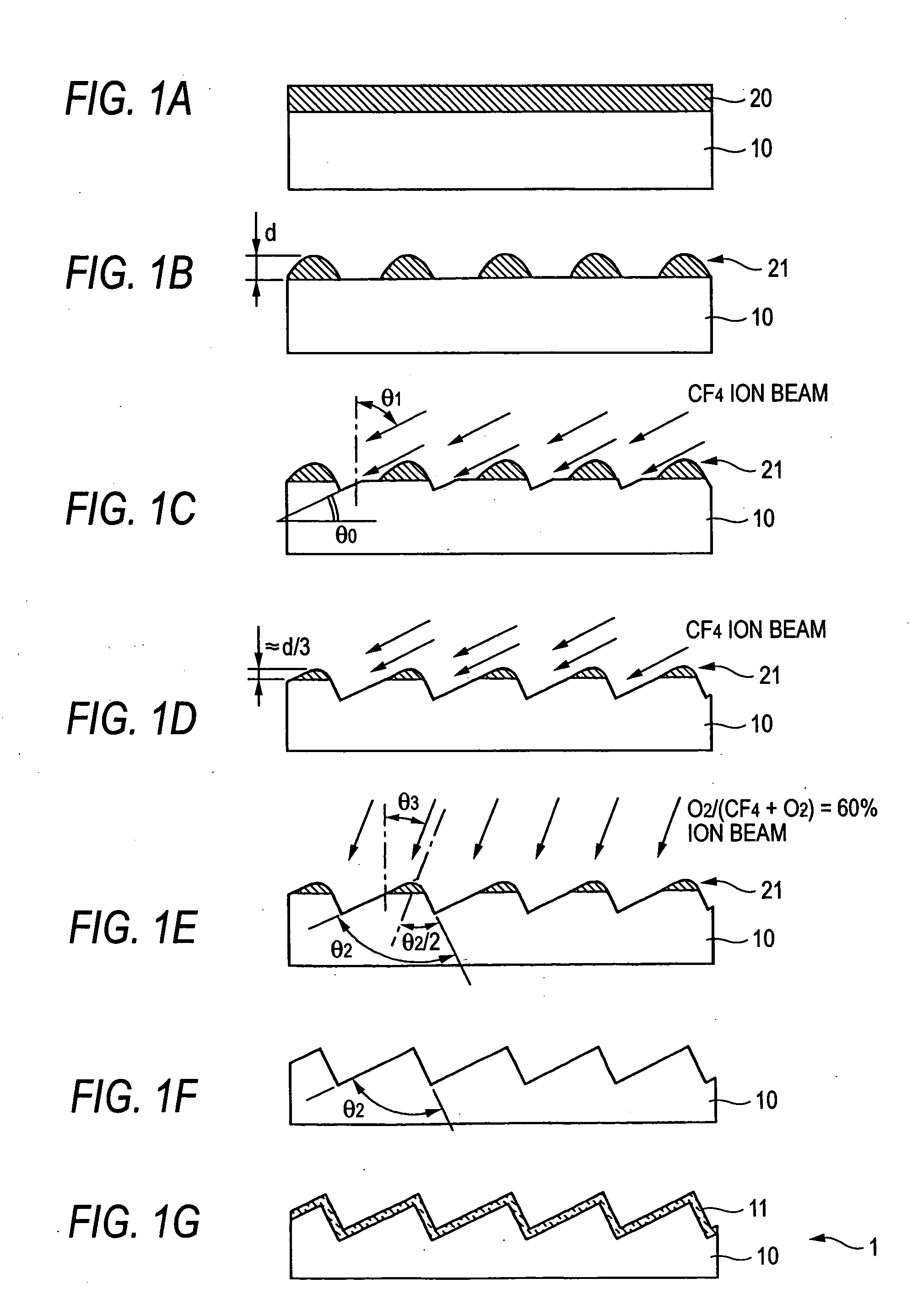
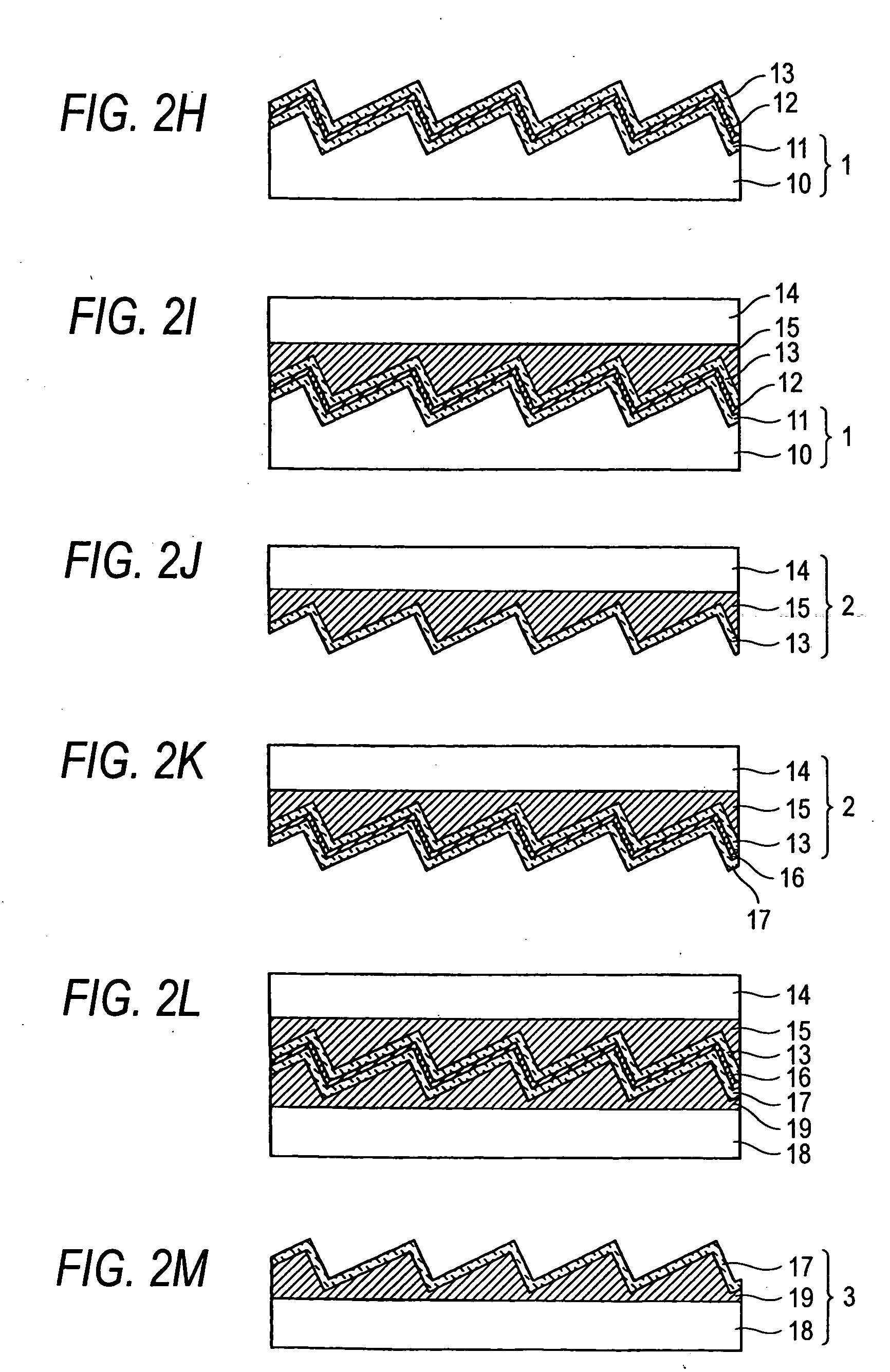
[0034] An embodiment of the method for the production of a blazed holographic grating (hereinafter referred to as “BHG”) according to the invention will be described in connection with FIG. 1. FIGS. 1 and 2 each are a schematic sectional view of various steps in the present embodiment of the method for the production of BHG. FIG. 3 is a schematic optical path diagram of a holographic exposure device for use in the production method of the invention.

(1) Step of Forming Photoresist Layer

[0035] In FIG. 1A, a substrate 10 made of optical glass is a blank for preparing an original grating. By way of example, BK7 glass is used herein. The kind of the substrate 10 is not limited so far as it can be optically polished so that it can be coated with a photoresist. In general, optical glass has a low thermal expansion coefficient and thus can be preferably used as a grating substrate material. Besides BK7, low thermal expansion crystalline glass such as BSC2, Pyrex (trade name of product of...


PUM


Abstract

A substrate is subjected to holographic exposure to a sinusoidal or half-sinusoidal resist pattern corresponding to grating groove thereon. Thereafter, the substrate and the resist pattern are subjected to a first etching step at which they are irradiated with an ion beam obliquely at an angle that is identical to the blaze angle in the presence of CF4 as an etching gas, whereby they are cut until the height of the resist is about ⅓ of the initial value. Thereafter, the substrate is subjected to a second etching step at which the substrate is irradiated with an ion beam in the direction corresponding to the bisector of the vertex in the presence of a mixture of CF4 and O2 as an etching gas, whereby the substrate is cut until the resist disappears completely to an extent such that some overetching occurs.

Description

BACKGROUND OF THE INVENTION [0001] 1. Field of the Invention [0002] The present invention relates to a grating (diffraction grating) which is a wavelength separating / selecting element for use in spectroscope, optical spectrum analyzer, WDM monitor, wavelength separator, etc. and a method for producing the grating. More particularly, the present invention relates to a blazed holographic grating prepared by a holographic exposure method and a method for producing the blazed holographic grating. [0003] 2. Description of the Related Art [0004] A grating (diffraction grating) is a wavelength separating / selecting element for use in spectroscope, wavelength separator, etc. Various gratings are known by the profile of section of groove. These gratings include one called “blazed holographic grating (BHG)”. [0005] As a basic method for producing the blazed holographic grating there has been heretofore known one disclosed in Japanese Patent No. 1,046,763. In accordance with the production meth...

Claims


Application Information

Patent Timeline
IPC IPC(8): G02B5/18B29D11/00G03C5/00G03F7/20G03H1/18
CPCG02B5/1857G03H2260/63G03H2260/14G03H1/182
Inventor KOEDA, MASARU
Owner SHIMADZU CORP
Why Eureka
Try Eureka