
Startup combustor for a fuel cell

Inactive Publication Date: 2005-06-16
NISSAN MOTOR CO LTD
View PDF5 Cites 15 Cited by
  • Summary
  • Abstract
  • Description
  • Claims
  • Application Information

AI Technical Summary

Benefits of technology

[0007] An advantage of the present invention is a startup combustor having a filter that is arranged upstream of a fuel reformer, which traps soot generated at startup. During the startup period, the startup combustor functions to regenerate the filter by burning, i.e., oxidizing, the trapped soot by combusting a lean fuel-air mixture in the startup combustor thereby regenerating the filter while continuously heating downstream system components.
[0008] These and other advantages are satisfied, at least in part, by a fuel 
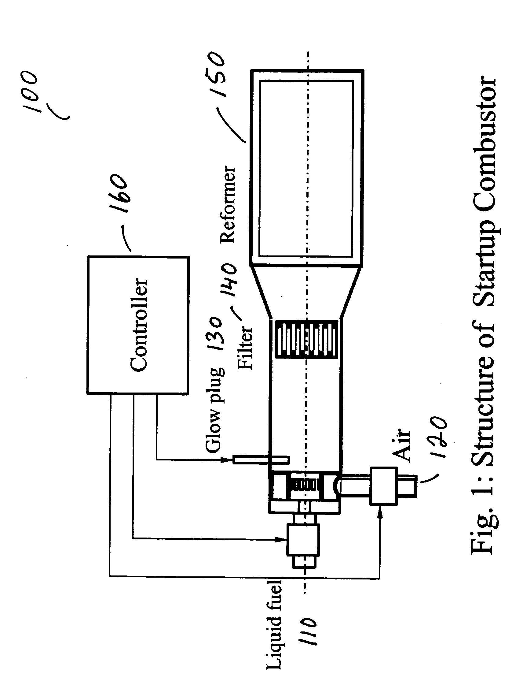
processing system that includes a startup combustor having a filter. In an embodiment of the present invention, the startup combustor comprises a chamber for combusting fuel; an air port connected to the chamber for introducing air to the chamber; a fuel port connected to the chamber for introducing fuel to the chamber; an ignition source connected to the chamber for igniting the fuel and air introduced thereto; and a filter that is connected to or included in the chamber which is located downstream of the ignition source for trapping any non-gaseous components, i.e., soot. The filter is advantageously capable of preventing at least a portion of any non-gaseous particles that may be formed during the combustion of the fuel in the chamber at the ignition source from passing therethrough. The filter can also prevent at least a portion of any non-gaseous particles contained in the air or fuel introduced to the chamber from passing through it as well.
[0009] Advantageously, the startup combustor functions to regenerate the filter by burning and eliminating the trapped soot by a lean-fuel combustion in the startup combustor, which can be accomplished by introducing an excess air to fuel ratio. For example, in regenerating the filter, an air compressor can control the volume of air introduced to the combustor; a fuel injector can control the amount of fuel to the combustor; and a computer can be programmed to control the rotation speed of the air compressor and the pulse width of the fuel injector according to operating condition. Each control parameter can be set by experiment in advance.
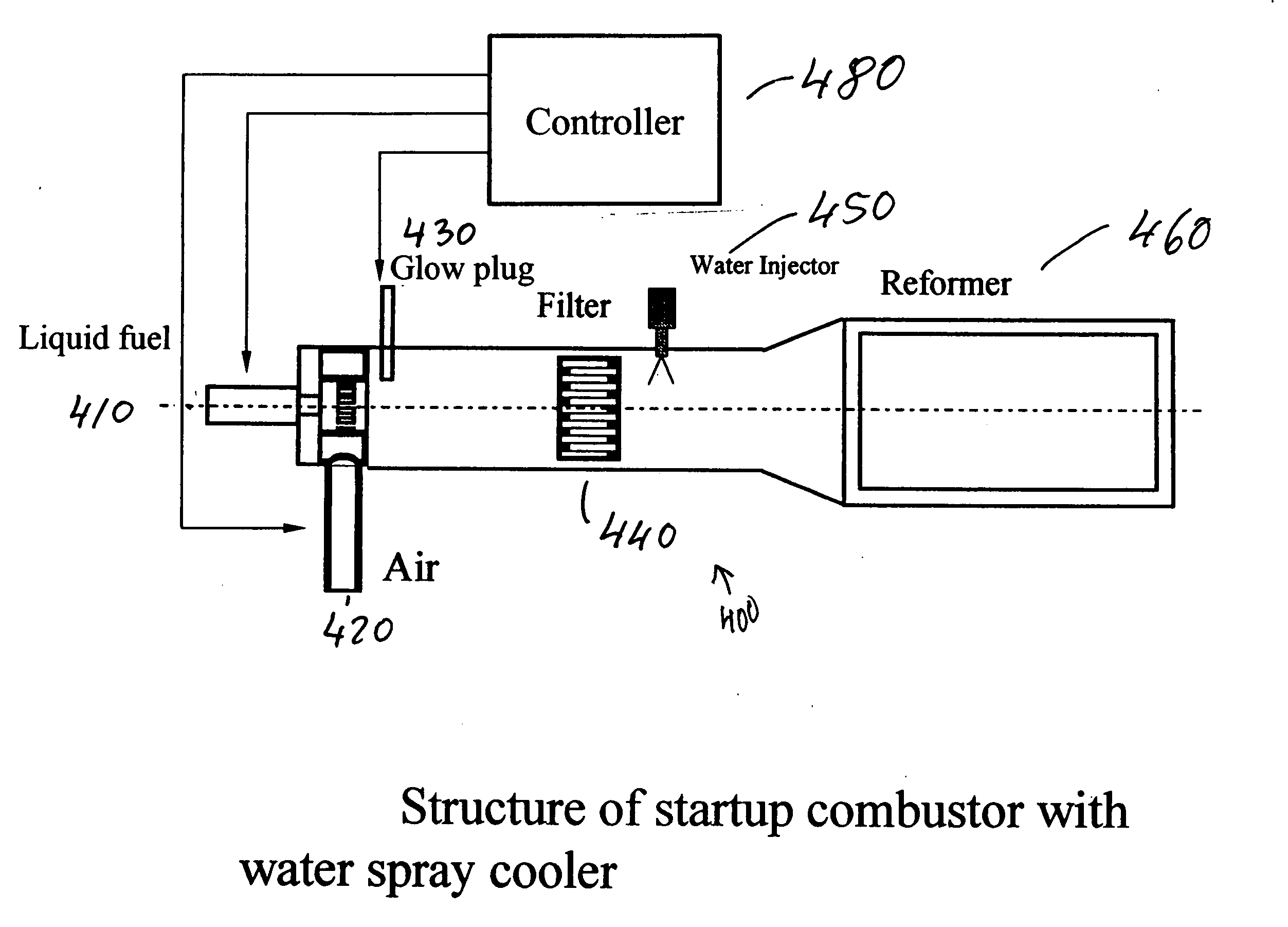
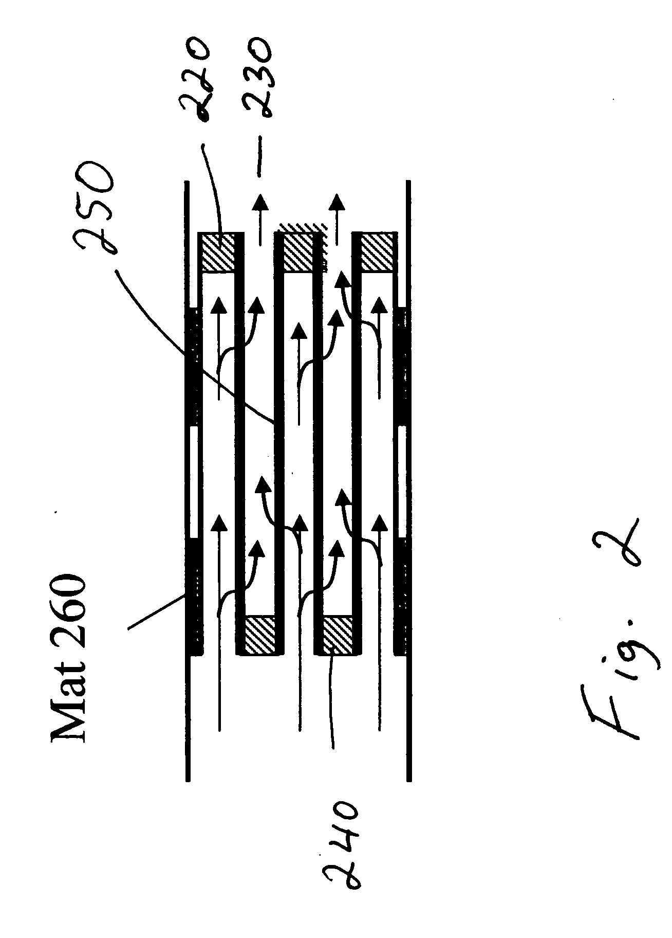
[0010] Embodiments of the present invention include a series of filters in or connected to the combustor which are located downstream of the ignition source or where combustion takes place; a port for introducing a cooling source to cool the outflow of gases exiting the one or more filters; a pressure gauge for detecting the pressure across the one or more filters at any given time; a reformer downstream of the filter for reforming the hydrocarbon fuel; a water / gas shift reactor downstream of the reformer for further reforming the hydrocarbon fuel; and a preferential catalyst downstream of the water / gas shift reactor for oxidizing various components contained in the reformed fuel.
[0011] Another aspect of the present invention includes a process for removing non-gaseous components, e.g., soot, in a combustor which are collected on a filter downstream of where combustion takes place. The process comprises combusting a hydrocarbon fuel to form a combustion gas stream that is then passed through a filter. As used herein, a combustion gas stream is meant the gases resulting from the combustion of a hydrocarbon fuel in a combustor. While the combusted gases contain carbon, hydrogen and oxygen based products, the gases are not limited thereto. The combustion gas stream at times can contain solid particles, which are likely carbon based. The combustion in this aspect of the invention takes place before the gases reach the reformer. The combusted gases are then passed through a filter, which collects or traps any solid particles contained in the combusted gas, referred to herein as soot. This soot can be reduced or eliminated from the filter by burning the fuel in the combustor at a leaner air-fuel mixture. Hence, the present invention advantageously permits the regeneration of the filter associated with the combustor while the combusted gases are continuously heating downstream components of the fuel processing system.
[0012] Embodiments of the present process includes determining the temperature of gases exiting the filter, i.e., the filter outflow temperature, and adjusting the temperature of the gases exiting the filter with a cooling source so that the inlet temperature of the reformer or any other component downstream of the combustor and the filter do not experience excessive temperatures that may degrade their performance.

Problems solved by technology

A typical problem in such fuel reforming systems is the generation of soot within the system due to the incomplete combustion of hydrocarbon fuel.
Soot can contaminate catalysts and other system components thereby adversely affecting the system's operation.

Method used


Image

  • Startup combustor for a fuel cell
  • Startup combustor for a fuel cell
  • Startup combustor for a fuel cell

Examples


example 1

[0061] Gasoline is used as the hydrocarbon fuel. The fuel processing catalytic system includes a reformer, a water gas shift reactor (WGS), and a selective CO eliminating reactor (preferential oxidizer, PROX). To warm up the fuel processing system at startup, fuel and air are introduced into the mixer of the startup combustor and mixed, and fuel is burned using a glow plug. For this purpose, the air and fuel injection rate is set to an excess air ratio of 3, and the gas temperature directly before the filter is approximately 900° C.

[0062] When this is done, a minimal quantity of soot is produced during combustion of fuel with air. However, since a filter is provided at the farthest downstream point of the combustion zone, soot is trapped and eliminated from the startup combustion gas, which is supplied to the reformer to increase its temperature.

[0063] The filter is composed of materials that have a heat resistance of 1000° C. or more, such as SiC, cordierite, and ceramic fiber, a...

example 2

[0067] Implementation of Example 2 is the same as implementing Example 1, except that soot accumulation amount is captured by calculations based on soot formation amount per unit time, as established by tests taking soot accumulation amount at previous startups as a baseline.

example 3

[0068] Implementation of Example 3 is the same as implementing Example 1, except that gas temperature at filter outflow is adjusted by cooling with a water spray.


PUM


Abstract

A combustor having a filter used to trap soot generated during its operation that is arranged upstream of a fuel reformer, is disclosed. During a startup period, the combustor functions to regenerate the filter by burning the trapped soot with a lean fuel-air mixture thereby regenerating the filter while continuously heating downstream components.

Description

FIELD OF THE INVENTION [0001] The invention relates to a startup combustor for a fuel reforming system and particularly to a combustor used to warm up a fuel reformer that generates a reformate stream containing hydrogen. [0002] Fuel cells have been developed as alternative power sources such as for electrical vehicles. A fuel cell is a demand-type power system in which the fuel cell operates in response to the load imposed across the fuel cell. Typically, a hydrocarbon fuel such as gasoline, methanol, diesel, naphtha, etc. serves as a fuel supply for the fuel cell. During operation, the fuel is converted to a gaseous stream containing hydrogen. The conversion is usually accomplished by passing the fuel through a fuel reformer to convert the hydrocarbon to a hydrogen gas stream. The hydrogen is then used by the fuel cell to generate electricity to power the vehicle. [0003] In a gasoline reformation process, steam, air and gasoline are reacted in a fuel processor which typically cont...

Claims


Application Information

Patent Timeline
IPC IPC(8): F23N1/02C01B3/38F23N5/20H01M8/00H01M8/04H01M8/06
CPCY02T50/677F23N5/20Y02T50/60
Inventor KAMIJO, MOTOHISA
Owner NISSAN MOTOR CO LTD
Features
  • Generate Ideas
  • Intellectual Property
  • Life Sciences
  • Materials
  • Tech Scout
  • Unparalleled Data Quality
  • Higher Quality Content
  • 60% Fewer Hallucinations
Learn More