Photocatalyst carrier

a photocatalyst and carrier technology, applied in the field of photocatalyst carriers, can solve the problems of high energy consumption, unsustainable, unsustainable, etc., and achieve the effect of enhancing the activity of the photocatalyst and the chemical reaction efficiency

Inactive Publication Date: 2005-06-16
IND TECH RES INST
View PDF8 Cites 8 Cited by
  • Summary
  • Abstract
  • Description
  • Claims
  • Application Information

AI Technical Summary

Benefits of technology

[0004] The primary object of the present invention is to provide a photocatalyst carrier capable of enhancing the activity of the photocatalyst and the chemical reaction efficiency.

Problems solved by technology

Obviously, such technology of conversion using heat to improve the reaction efficiency will require lots of energy for providing the high-temperature environment.
Hence, converting a waste substance into a energy source by using heat and catalyst is not cost-effective, and also is not environmentally friendly.
However, if the excited electrons cannot be consumed effectively, the electrons accumulated at the intersection of the conductive carrier and the photocatalyst.
As a result, such photocatalyst is not ideal for industrial processes and requires an immediate improvement.

Method used


Image

  • Photocatalyst carrier
  • Photocatalyst carrier
  • Photocatalyst carrier

Examples


Embodiment Construction

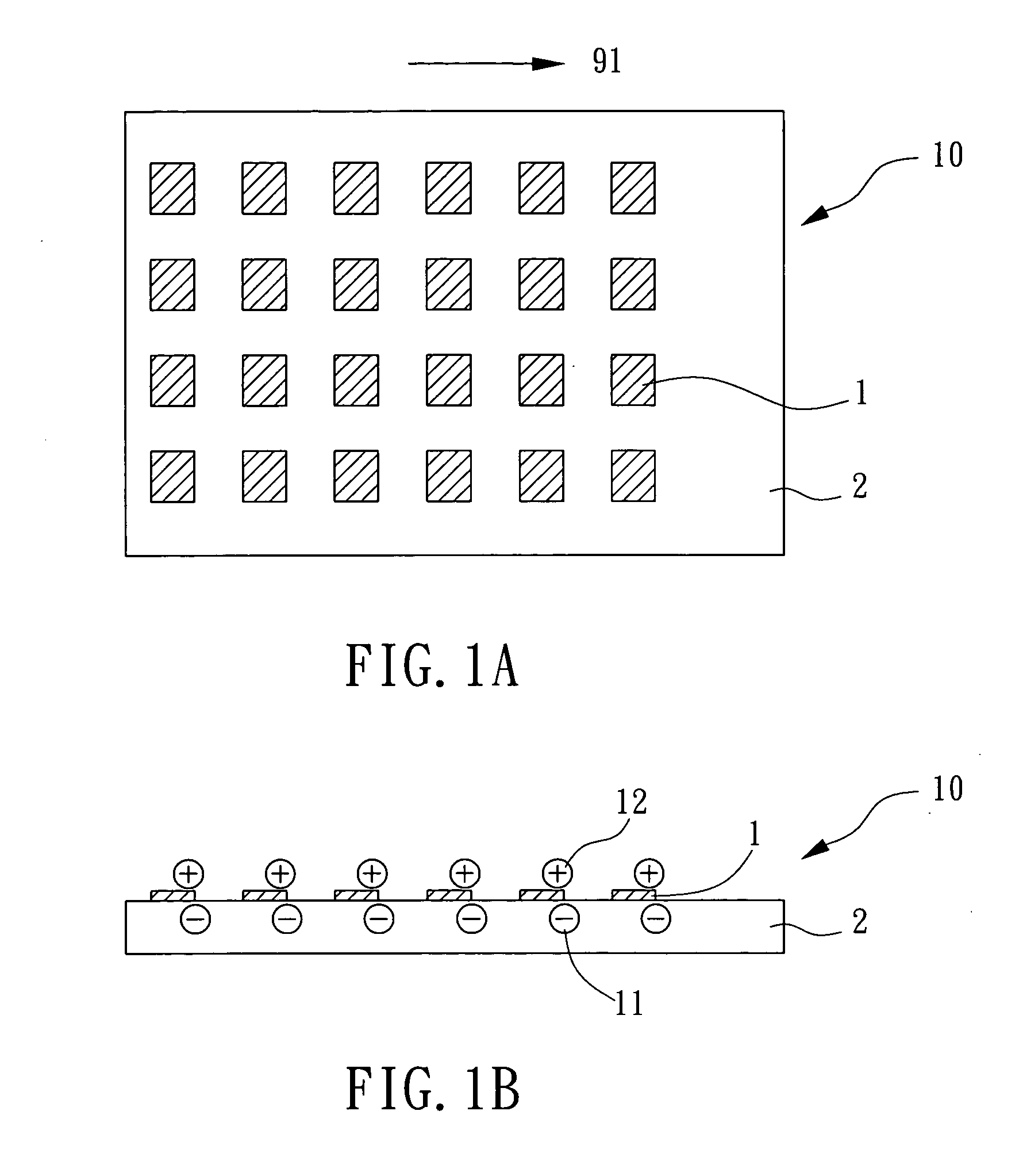
[0012] The photocatalyst carrier of the present invention is an improved photo-reactor, capable of enhancing the life time of the electron-hole pair and the photocatalyst activity by using the concept of photoelectron transmission and separation.

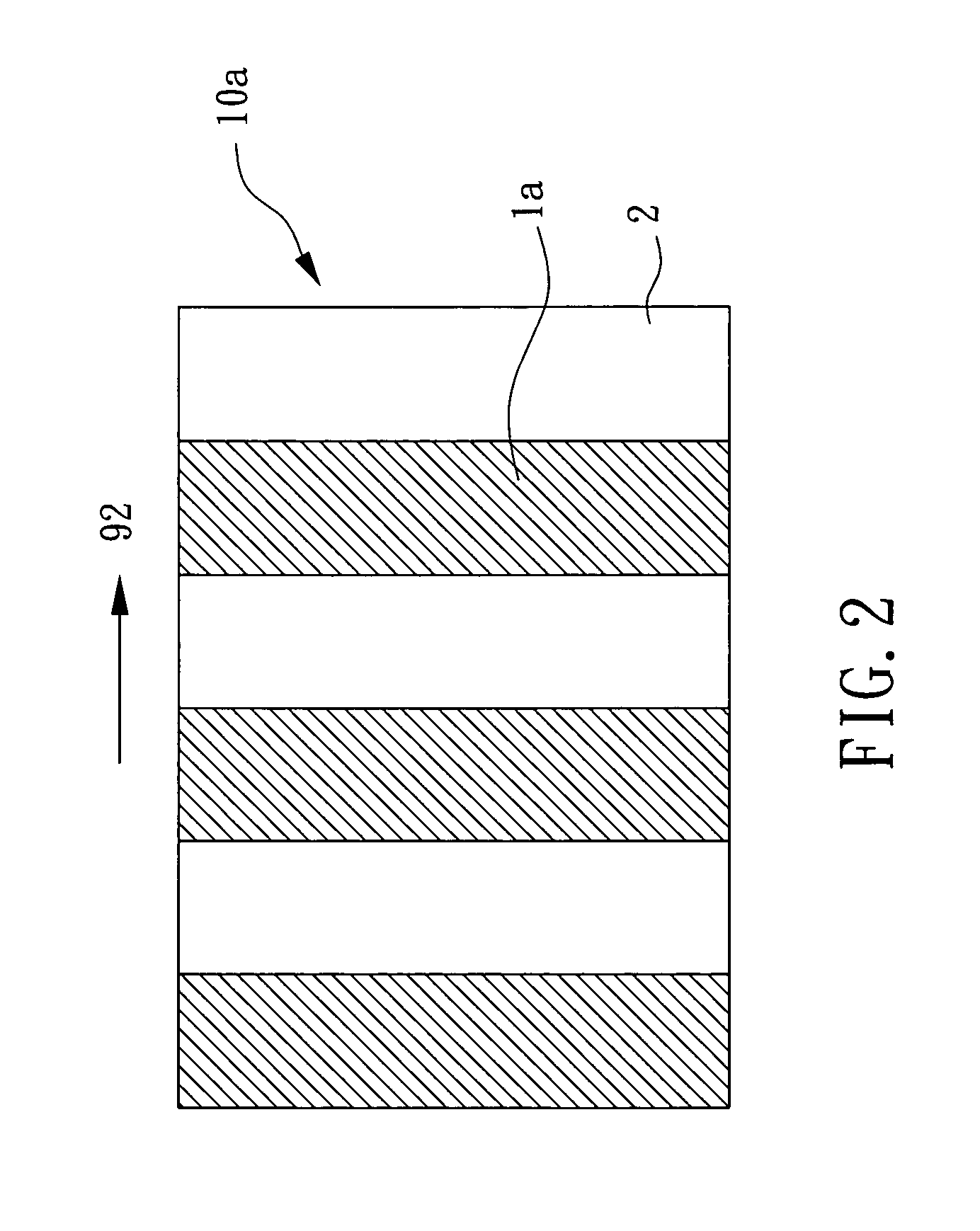
[0013] Please refer to FIG. 1A and FIG. 1B for the top view and side view of the photocatalyst carrier respectively. The photocatalyst carrier 10 comprises a carrier 2 and a photocatalyst 1. The carrier 2 is an electric-conductive-material-made rectangular board with a surface, and the electric conductive material could be copper, iron, aluminum, conductive glass or semiconductor known to those skilled in the art. The photocatalyst 1 is a thin-film photocatalyst, and the thickness of the film could be several nanometers to several millimeters, moreover, the photocatalyst 1 could be made of material containing such as titanium (Ti), zinc (Zn), tungsten (W), tin (Sn), Chromium (Cr), tantalum (Ta), and zirconium (Zr) or other derivative, and i...


PUM

PropertyMeasurementUnit
temperatureaaaaaaaaaa
electric conductiveaaaaaaaaaa
distanceaaaaaaaaaa

Abstract

A photocatalyst carrier comprises a carrier and a photocatalyst, wherein the carrier having a surface is made of an electric conductive material, and the photocatalyst is coated unevenly onto the surface to form a plurality of photocatalyst electrodes. By applying the concept of electronic transmission, the existence probability of the electron-hole pair is increased for enabling the reactant to perform an oxidation-reduction reaction on the photocatalyst and carrier respectively so as to enhance the photocatalyst activity.

Description

1. FIELD OF THE INVENTION [0001] The present invention relates to a photocatalyst carrier, more particularly, to a photocatalyst carrier consisting of a conductive carrier unevenly coated with a photocatalyst. 2. DESCRIPTION OF THE PRIOR ARTS [0002] In the development of sustainable energy, methods of converting waste substances into reusable energy sources have become the most frequently discussed and studied subjects. Although converting waste into energy source is technologically feasible, external energy, such as heat, and light, etc., is required for this reaction. For instance, when carbon dioxide is used in the process of converting one into usable hydrocarbon materials, such as methane or methanol, by using a catalyst to lower the free activation enthalpy energy of the reaction, a huge amount of energy reaction is required for reaction since carbon dioxide is a material with high thermodynamic stability. If the energy is supplied by heat, high temperature (700˜1000° C.) is r...

Claims


Application Information

Patent Timeline
Patent Type & Authority Applications(United States)
IPC IPC(8): B01J21/06B01J35/00
CPCB01J21/06B01J35/004B01J35/0033B01J21/063
Inventor CHENG, KONG-WEIKUO, JU-CHIACHEN, SHIH-PUHUANG, JAU-CHYN
Owner IND TECH RES INST
Why Eureka
Try Eureka