Switching power supply apparatus and electric applianance therewith

Inactive Publication Date: 2005-06-23
SHARP KK
View PDF0 Cites 33 Cited by
  • Summary
  • Abstract
  • Description
  • Claims
  • Application Information

AI Technical Summary

Benefits of technology

[0030] With this configuration, in the normal condition, where the overcurrent detection portion does not operate, the switching operation of the switching device is performed based solely on the first current-compensated signal that is current-compensated by the first current compensation portion. Thus, even when the switching device is switched with a high duty, it does not cause low-frequency oscillation. On the other hand, in the overcurrent-protection-enabled condition, where the overcurrent detection portion operates, the overcurrent detection portion is operated based solely on the second current-compensated signal that is current-compensated by the second current compensation portion. Thus, even when the switching device is switched with a high duty, it does not cause low-frequency oscillation. In this way, both in the normal and overcurrent-protection-enabled conditions, even when the switching device is switched with a high duty, the switching frequency can be stabilized. This makes it possible to reduce the inductance and capacitance of the coil and capacitor used, and thereby to make the switching power supply apparatus compact and inexpensive.
[0031] According to the present invention, the second current compensation portion super

Problems solved by technology

In switching power supply apparatuses of the so-called current-control type, i.e., those that determine the on/off ratio (duty) of the switching device by comparing the output voltage with the switch current flowing through the switching device, it is known that a duty higher than 50% provokes unstable operation, causing low-frequency oscillation.
When low-frequency oscillation occurs, the switching frequency usually drops to a fraction of its normal frequency, producing undesirable effects including increased ripples in the output voltage.
As a result, when the switching operation is performed with a high duty, low-frequency oscilla

Method used


Image

  • Switching power supply apparatus and electric applianance therewith
  • Switching power supply apparatus and electric applianance therewith
  • Switching power supply apparatus and electric applianance therewith

Examples


first embodiment

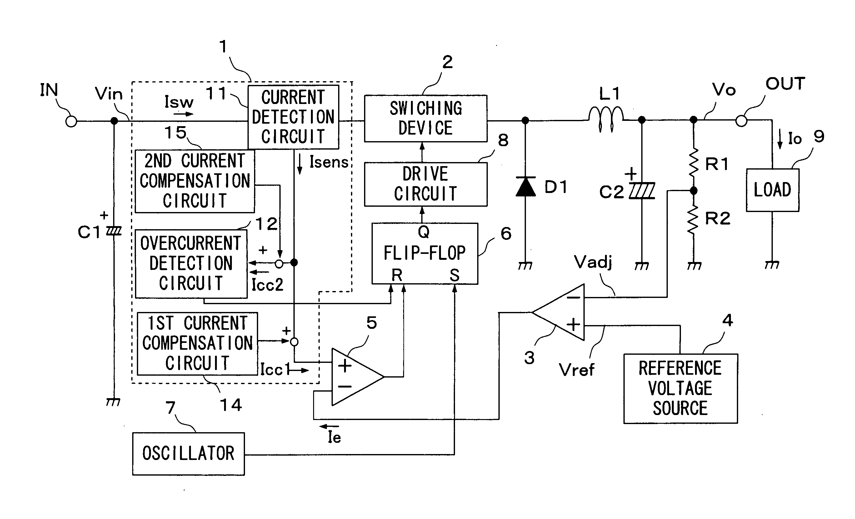
[0051] Hereinafter, embodiments of the present invention will be described with reference to the accompanying drawings. FIG. 1 is a circuit block diagram showing the electrical configuration of the switching power supply apparatus of the invention. In FIG. 1, such circuit components and blocks as find their counterparts in FIG. 6 are identified with common reference numerals and symbols, and their explanations will not be repeated. The switching power supply apparatus shown in FIG. 1 differs from the switching power supply apparatus shown in FIG. 6 in that, within the current control portion 1, a first current compensation circuit (first current compensation portion) 14 is provided instead of the current compensation circuit 13, and that a second current compensation circuit (second current compensation portion) 14 is additionally provided.

[0052] The first current compensation circuit 14 is configured and operates in similar manners to the current compensation circuit 13 shown in FI...

second embodiment

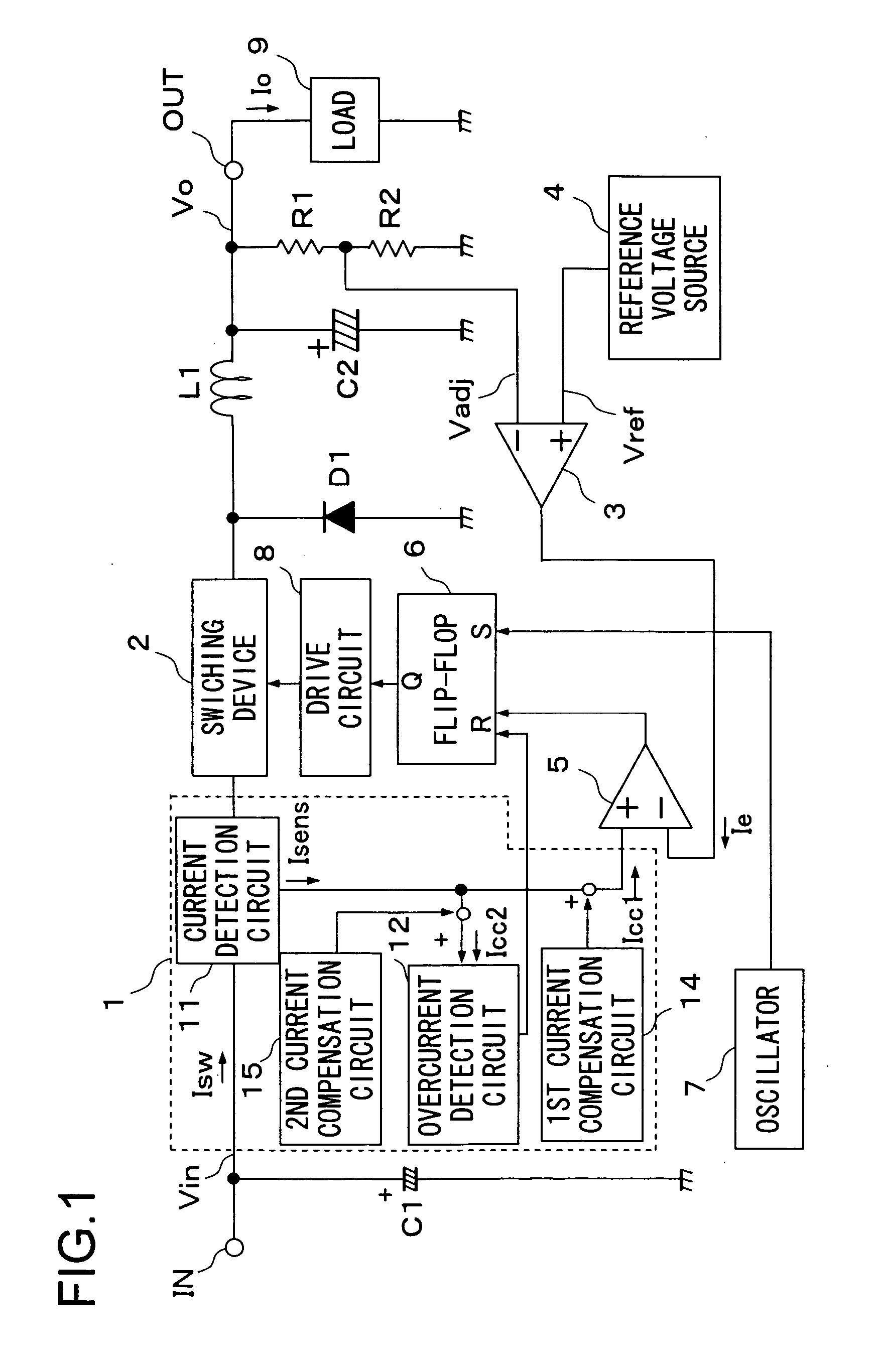
[0057]FIG. 2 is a circuit block diagram showing the electrical configuration of the switching power supply apparatus of the invention. In FIG. 2, such circuit components and blocks as find their counterparts in FIG. 1 are identified with common reference numerals and symbols, and their explanations will not be repeated. The switching power supply apparatus shown in FIG. 2 differs from the switching power supply apparatus shown in FIG. 1 in that, within the current control portion 1, a flip-flop (latch portion) 16 is additionally provided between the overcurrent detection circuit 12 and the second current compensation circuit 15.

[0058] The flip-flop 16 receives, at the set input terminal S thereof, the set signal (overcurrent detection signal) from the overcurrent detection circuit 12, and, at the reset input terminal R thereof, the output signal of the comparator 5. The output signal from the output terminal Q of the flip-flop 16 is fed to the second current compensation circuit 15....

third embodiment

[0062]FIG. 3 is a circuit block diagram showing the electrical configuration of the switching power supply apparatus of the invention. In FIG. 3, such circuit components and blocks as find their counterparts in FIG. 2 are identified with common reference numerals and symbols, and their explanations will not be repeated. The switching power supply apparatus shown in FIG. 3 differs from the switching power supply apparatus shown in FIG. 2 in that the set signal fed from the overcurrent detection circuit 12 to the flip-flop 16 is not used and instead an AND gate (logic gate) 17 is additionally provided that outputs a set signal with which the flip-flop 16 is set.

[0063] The AND gate 17 is a two-input, one-output AND gate. The AND gate 17 receives, at one input, the pulse signal from the oscillator 7 and, at the other input, the output signal of the flip-flop 6. The output signal of the AND gate 17 is used as a set signal for the flip-flop 16.

[0064] In the overcurrent condition, the on-...


PUM


Abstract

A switching power supply apparatus produces an output voltage by smoothing a pulsating voltage obtained by switching an input direct-current voltage with a switching device. The switching power supply apparatus has a current detection circuit that outputs a detection current that varies in proportion to the switch current flowing through the switching device, an overcurrent detection circuit that detects an overcurrent by comparing the detection current with a set current previously set so as to correspond to the overcurrent detection level and that, on detection of an overcurrent, feeds a reset signal to a flip-flop for controlling the switching of the switching device to turn the switching device off, and a second current compensation circuit that superimposes a compensation current on the detection current fed to the overcurrent detection circuit to produce a compensated current.

Description

[0001] This nonprovisional application claims priority under 35 U.S.C. § 119(a) on Patent Application No. 2003-422358 filed in Japan on Dec. 19, 2003, the entire contents of which are hereby incorporated by reference. BACKGROUND OF THE INVENTION [0002] 1. Field of the Invention [0003] The present invention relates to a switching power supply apparatus, and to an electric appliance incorporating it. More particularly, the present invention relates to a switching power supply apparatus provided with an overcurrent protection function whereby the output current is limited in an overloaded condition, and to an electric appliance incorporating such a switching power supply apparatus. [0004] 2. Description of Related Art [0005] There has invariably been a strong demand for size and cost reduction in switching power supply apparatuses and in electric appliances incorporating them. In response, in switching power supply apparatuses, size and cost reduction has been attempted and achieved by...

Claims


Application Information

Patent Timeline
IPC IPC(8): H02M3/156H02M3/155
CPCH02M1/32H02M2001/0025H02M3/156H02M1/0025
Inventor KANAMORI, ATSUSHIOKI, KAZUFUMI
Owner SHARP KK
Why Eureka
Try Eureka