Reduced degradation of ion-exchange membranes in electrochemical fuel cells

a technology of ion exchange membrane and fuel cell, which is applied in the manufacture of fuel cells, fuel cells, electrical equipment, etc., can solve the problems of increased mea loading of additives, fuel cell performance loss, and unintended consequences, and achieves increased susceptibility to membrane degradation and loading of additives

Active Publication Date: 2005-06-23
BDF IP HLDG
View PDF11 Cites 89 Cited by
  • Summary
  • Abstract
  • Description
  • Claims
  • Application Information

AI Technical Summary

Benefits of technology

[0015] In particular, the non-uniform support may be in the x-y plane of the MEA and not in the through plane (z-direction) of the MEA. In some embodiments, there may be an increased loading of the additive in regions of the MEA that are more susceptible to membrane degradation. In some embodiments, such regions of increased susceptibility to membrane degradation are in the inlet and / or outlet regions of the MEA.
[0016] Non-uniform support may mean that the loading of the additive varies across the x-y plane or alternatively, that there are regions of the MEA with little to no additive present. For example, there may be less than 80% coverage of the additive in the x-y plane. In a more particular embodiment, there may be less than 50% or less than 25% coverage of the additive in the x-y plane. For example, there may be between 1 and 25%, more particularly between 10 and 25% and even more particularly between 15 and 25% coverage of the additive in the x-y plane.

Problems solved by technology

However, there may be unintended consequences by such an application of an additive to either the ion-exchange membrane or a catalyst layer.
For example, a fuel cell may suffer a performance loss with the application of such an additive.
In some embodiments, there may be an increased loading of the additive in regions of the MEA that are more susceptible to membrane degradation.
Non-uniform support may mean that the loading of the additive varies across the x-y plane or alternatively, that there are regions of the MEA with little to no additive present.

Method used


Image

  • Reduced degradation of ion-exchange membranes in electrochemical fuel cells
  • Reduced degradation of ion-exchange membranes in electrochemical fuel cells
  • Reduced degradation of ion-exchange membranes in electrochemical fuel cells

Examples


examples

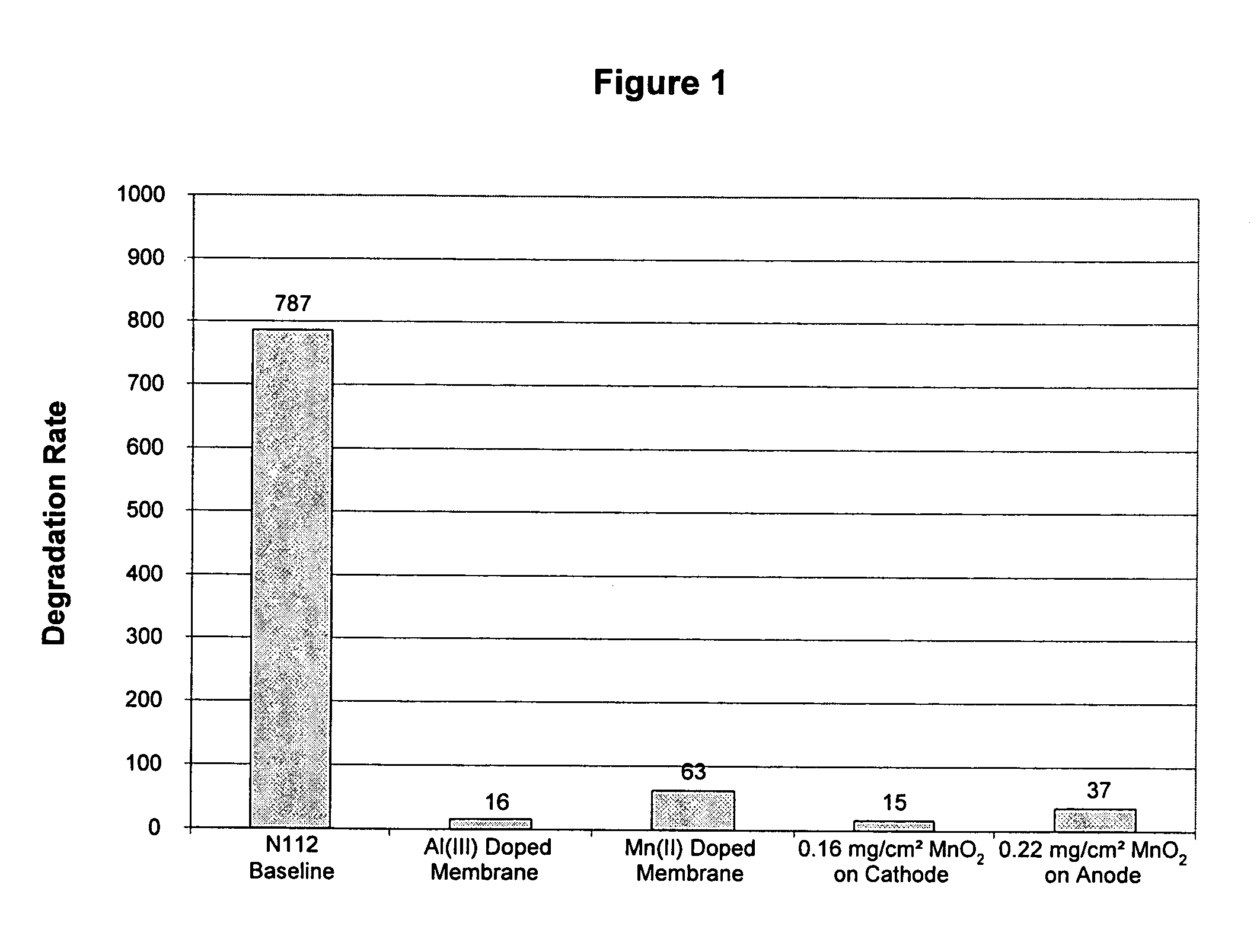
Nafion® 112 Doped with Al(III) or Mn(II)

[0050] Multivalent cations were ion-exchanged into the membrane by soaking the membrane in an aqueous solution of the appropriate cation overnight. Nafion® 112 membranes were used as received. Reagent grade Al2(SO4)3.xH2O (Aldrich) and MnSO4 (Aldrich) were used as appropriate without further purification. Solutions were prepared in deionized water with the amount of salt added calculated based on the percentage of sulfonic acid sites to be exchanged and taking into account the valency of the cation. A nominal equivalent weight value of 1050 g / mol for Nafion® 112 was used to calculate the moles of SO3-sites available per gram of membrane. Membranes were then rinsed with deionized water and immersed in deionized water for several hours. This process was completed at least 3 times, after which the membranes were allowed to air dry overnight between Kimwipes before bonding into a membrane electrode assembly.

Coating MnO2 on Cathode

[0051] A pre...


PUM

PropertyMeasurementUnit
output voltageaaaaaaaaaa
current densityaaaaaaaaaa
weightaaaaaaaaaa

Abstract

A significant problem in PEM fuel cell durability is in premature failure of the ion-exchange membrane and in particular by the degradation of the ion-exchange membrane by reactive hydrogen peroxide species. Such degradation can be reduced or eliminated by the presence of an additive in the anode, cathode or ion-exchange membrane. The additive may be a radical scavenger, a membrane cross-linker, a hydrogen peroxide decomposition catalyst and/or a hydrogen peroxide stabilizer. The presence of the additive in the membrane electrode assembly (MEA) may however result in reduced performance of the PEM fuel cell. Accordingly, it may be desirable to restrict the location of the additive to locations of increased susceptibility to membrane degradation such as the inlet and/or outlet regions of the MEA.

Description

BACKGROUND OF THE INVENTION [0001] 1 Field of the Invention [0002] The present invention relates to ion-exchange membranes and more particularly to ion-exchange membranes for electrochemical fuel cells. [0003] 2. Description of the Related Art [0004] Electrochemical fuel cells convert reactants, namely fuel and oxidant streams, to generate electric power and reaction products. Electrochemical fuel cells generally employ an electrolyte disposed between two electrodes namely a cathode and an anode. An electrocatalyst is needed to induce the desired electrochemical reactions at the electrodes. In addition to electrocatalyst, the electrodes may also comprise an electrically conductive substrate upon which the electrocatalyst is deposited. The electrocatalyst may be a metal black (namely, a substantively pure, unsupported, finely divided metal or metal powder) an alloy or a supported metal catalyst, for example, platinum on carbon particles. [0005] A proton exchange membrane (PEM) fuel c...

Claims


Application Information

Patent Timeline
Patent Type & Authority Applications(United States)
IPC IPC(8): H01M4/86H01M4/88H01M4/90H01M8/10
CPCH01M4/8605H01M4/8663H01M4/90H01M8/1004Y02E60/521H01M8/1039H01M8/1051H01M8/1053H01M8/1072H01M8/1023Y02P70/56
Inventor ANDREWS, NEIL R.KNIGHTS, SHANNA D.MURRAY, KENNETH A.MCDERMID, SCOTT J.MACKINNON, SEAN M.YE, SIYU
Owner BDF IP HLDG
Why Eureka
Try Eureka