
Manufacturing method of semiconductor device, semiconductor device, circuit substrate and electronic equipment

a manufacturing method and semiconductor technology, applied in semiconductor/solid-state device testing/measurement, semiconductor devices, semiconductor/solid-state device details, etc., can solve the problems of difficult to form wiring or the like on a polished surface, difficult to mount the electronic parts in the mounting space, and achieve the effect of inexpensive high-performance devices

Active Publication Date: 2005-06-23
SAMSUNG ELECTRONICS CO LTD
View PDF6 Cites 25 Cited by
  • Summary
  • Abstract
  • Description
  • Claims
  • Application Information

AI Technical Summary

Benefits of technology

The present invention provides a manufacturing method of a semiconductor device that simplifies the process of mounting semiconductor chips on a substrate. By embedding and forming a coupling terminal on the substrate and exposing it through a polishing process, the step of mounting semiconductor chips on the substrate is simplified as compared to conventional methods. The method also makes it easier to form rearrangement wiring on the substrate and to test each semiconductor device before mounting it. The semiconductor device is manufactured by this method, which provides an inexpensive high performance device.

Problems solved by technology

Moreover, these electronic parts are extremely limited in the mounting space.
However, it is technically difficult to form a wiring or the like on a polished surface, or the step becomes complicated by forming a new wiring layer.
However, such a dicing tape is required to be thin, so as a result, the substrate as the adhered sometimes cannot be sufficiently held (that is, oscillation occurs between the adhered and the tape).
When such oscillation occurs during cutting, there is a risk of chipping the substrate (chipping) when the tip end portion of the blade penetrates to the tape side from the substrate.

Method used


Image

  • Manufacturing method of semiconductor device, semiconductor device, circuit substrate and electronic equipment
  • Manufacturing method of semiconductor device, semiconductor device, circuit substrate and electronic equipment
  • Manufacturing method of semiconductor device, semiconductor device, circuit substrate and electronic equipment

Examples


Embodiment Construction

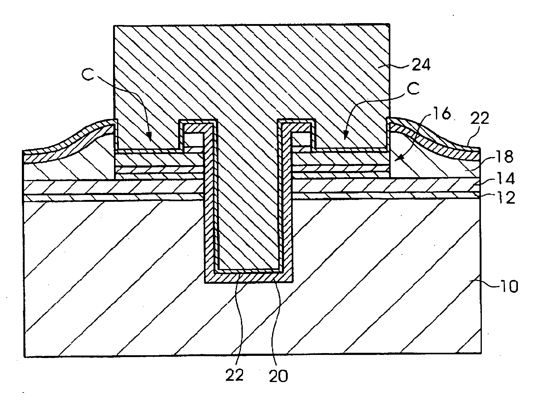
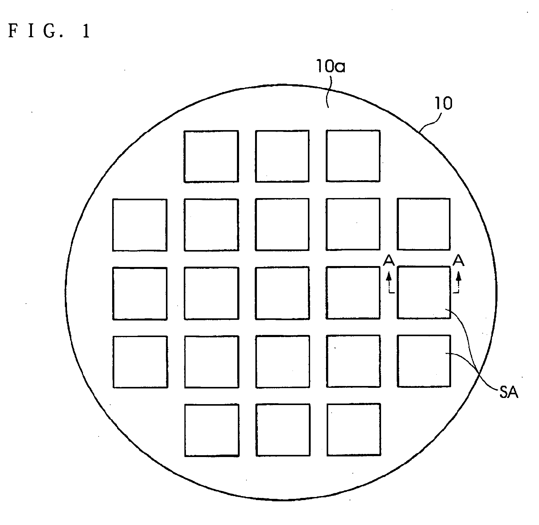
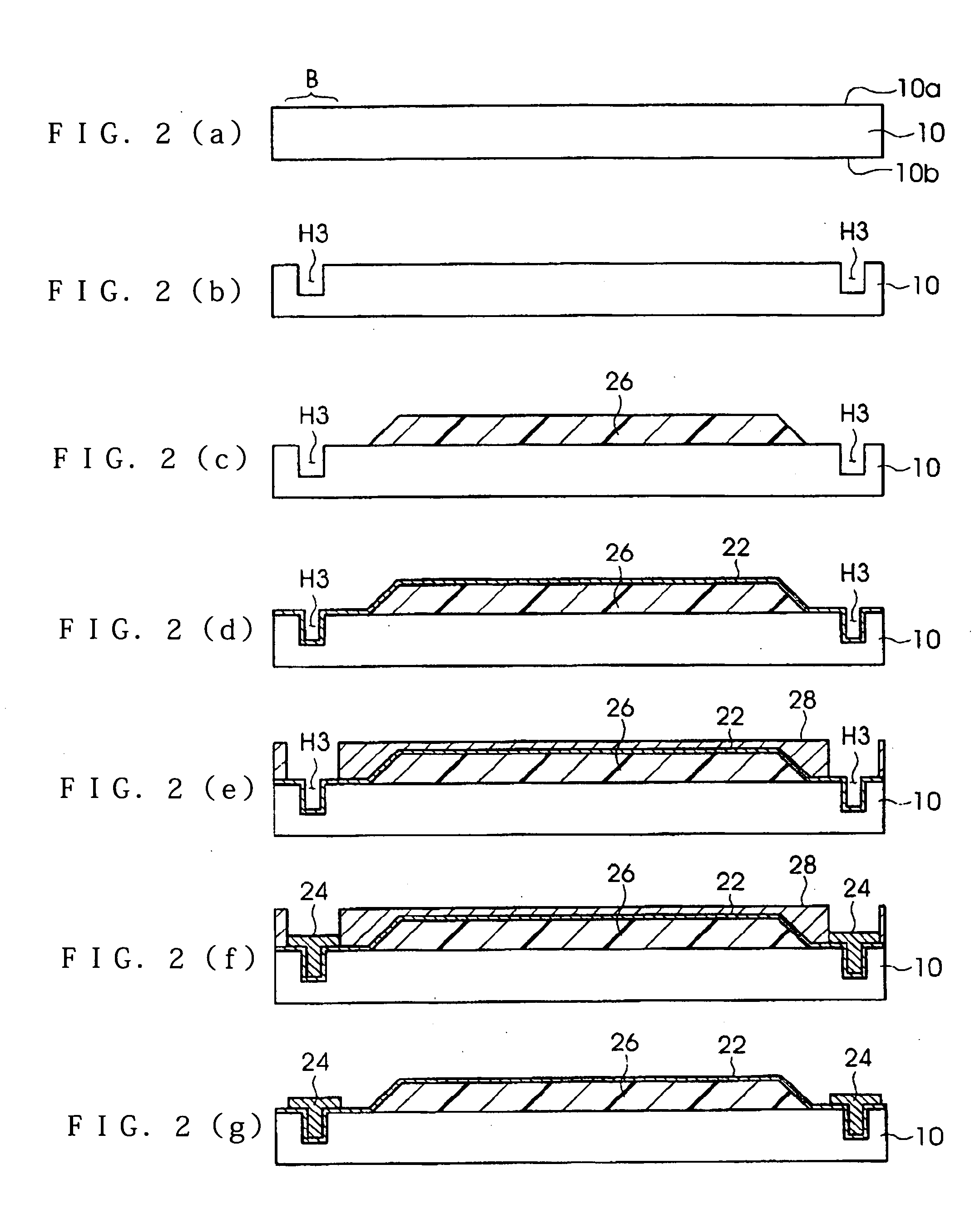
[0036] Hereinafter, referring to the drawing, a manufacturing method of a semiconductor device, a semiconductor device, and electronic equipment will be described in detail according to one embodiment of the present invention. The outline of the manufacturing method of the semiconductor device of the present embodiment has an aspect in the point that an individual semiconductor chip is deposited on a wafer (substrate) that is thinned, and the entire manufacturing step is generally classified into: a first step of processing a substrate on which the semiconductor chip is deposited; a second step of manufacturing the semiconductor chip to be deposited; and a third step of mounting the chip on the substrate. These steps may be carried out sequentially, and the first step and the second step maybe carried out in parallel. In view of the manufacturing efficiency, it is preferable to form the semiconductor chip in the second step in advance, and carry out the third step after the first st...


PUM


Abstract

A method of manufacturing a semiconductor device is provided. The method includes embedding and forming a coupling terminal as an external electrode of an electronic circuit on an active surface side of a substrate having an active surface formed with a plurality of electronic circuits, exposing a part of the coupling terminal by polishing a back surface side of the substrate, mounting a semiconductor chip on the back surface side of the substrate via the coupling terminal, sealing the semiconductor chip mounted on the substrate by a sealing material, and cutting the substrate for every forming area of each electronic circuit and dividing it into a plurality of semiconductor devices.

Description

RELATED APPLICATIONS [0001] This application claims priority to Japanese Patent Application No. 2003-420807 filed Dec. 18, 2003 which is hereby expressly incorporated by reference herein in its entirety.BACKGROUND [0002] 1. Field of the Invention [0003] The present invention relates to a manufacturing method of a semiconductor device, a semiconductor device, a circuit substrate and electronic equipment. [0004] 2. Related Art [0005] Currently, since electronic equipment having portability such as a portable phone, a notebook size personal computer, and a PDA (Personal data assistance), and equipment such as a sensor, a micro-machine, and a printer head are small sized and light weight, miniaturization of various electronic parts of a semiconductor chip or the like installed inside have been made. Moreover, these electronic parts are extremely limited in the mounting space. [0006] Therefore, research and development for manufacturing a micro semiconductor chip using a technology calle...

Claims


Application Information

Patent Timeline
Patent Type & Authority Applications(United States)
IPC IPC(8): H01L21/66H01L21/301H01L21/3205H01L21/768H01L23/12H01L23/48H01L23/52H01L25/00H01L25/065H01L25/07H01L25/18
CPCH01L21/561H01L21/76898H01L23/481H01L25/0657H01L2224/16H01L2225/06513H01L2225/06524H01L2225/06541H01L2225/06582H01L25/50H01L2224/02372H01L2224/05009H01L2224/05548H01L2224/05573H01L2224/05147H01L2224/05647H01L2224/02377H01L2224/05557H01L2224/16146H01L24/81H01L24/16H01L2224/06131H01L24/05H01L2924/00014H01L25/00H01L25/065
Inventor FUKAZAWA, MOTOHIKO
Owner SAMSUNG ELECTRONICS CO LTD
Learn More