Process for depositing composite coating on a surface

a composite coating and surface technology, applied in the direction of ion implantation coating, chemical vapor deposition coating, coatings, etc., can solve the problems of frequent machine downtime, easy release of ic packages, and the tendency of molding compounds to adhere to the encapsulation mold, so as to improve the ionisation of plasma

Inactive Publication Date: 2005-06-23
AGENCY FOR SCI TECH & RES
View PDF9 Cites 37 Cited by
  • Summary
  • Abstract
  • Description
  • Claims
  • Application Information

AI Technical Summary

Benefits of technology

[0005] The present invention provides an improved sputtering method to form a coating on a substrate surface. The coating is of a layered structure with a bonding layer, a transition interlayer and a functional layer. The method provides a biasing system where different types of power source are applied in sputtering a target for depositing the target material onto the substrate surface in the presence of a plasma. The types of power include a Direct Current (DC) power, a Radio Frequency (RF) power and a Pulsed Direct Current (PDC) power. The DC is applied to bias the target to generate ions and atomic clusters of the target material to form the bonding layer; the RF is applied to bias an electrode to improve ionisation of the plasma to form the intermediate and functional layer; and the PDC is applied to bias the substrate surface to induce alignment and growth of atoms and ions deposited on the substrate surface.

Problems solved by technology

A common problem that arises with the use of EMC is the tendency for these molding compounds to adhere to the encapsulation mold.
Therefore the encapsulated IC package tends to stick to the encapsulation mold and prevents easy release of the IC packages from the encapsulation mold.
As a result of the stickiness of the EMC, the encapsulation of IC can give low yield and cause frequent machine down time and can produce compromised quality of encapsulated IC packages.
However, these means are able to only provide ions at above 50% ionisation.
However, this has not been sufficient to affect the coating structure to produce dense coatings.

Method used


Image

  • Process for depositing composite coating on a surface
  • Process for depositing composite coating on a surface
  • Process for depositing composite coating on a surface

Examples


example

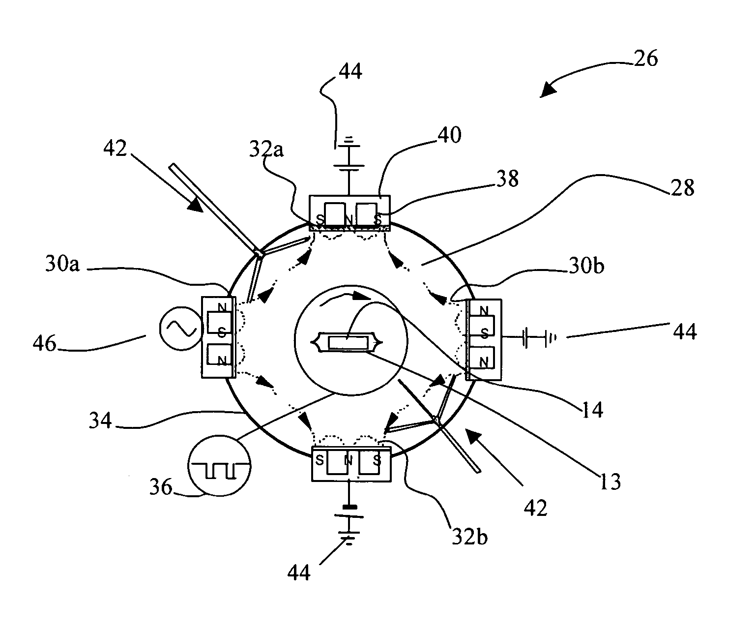
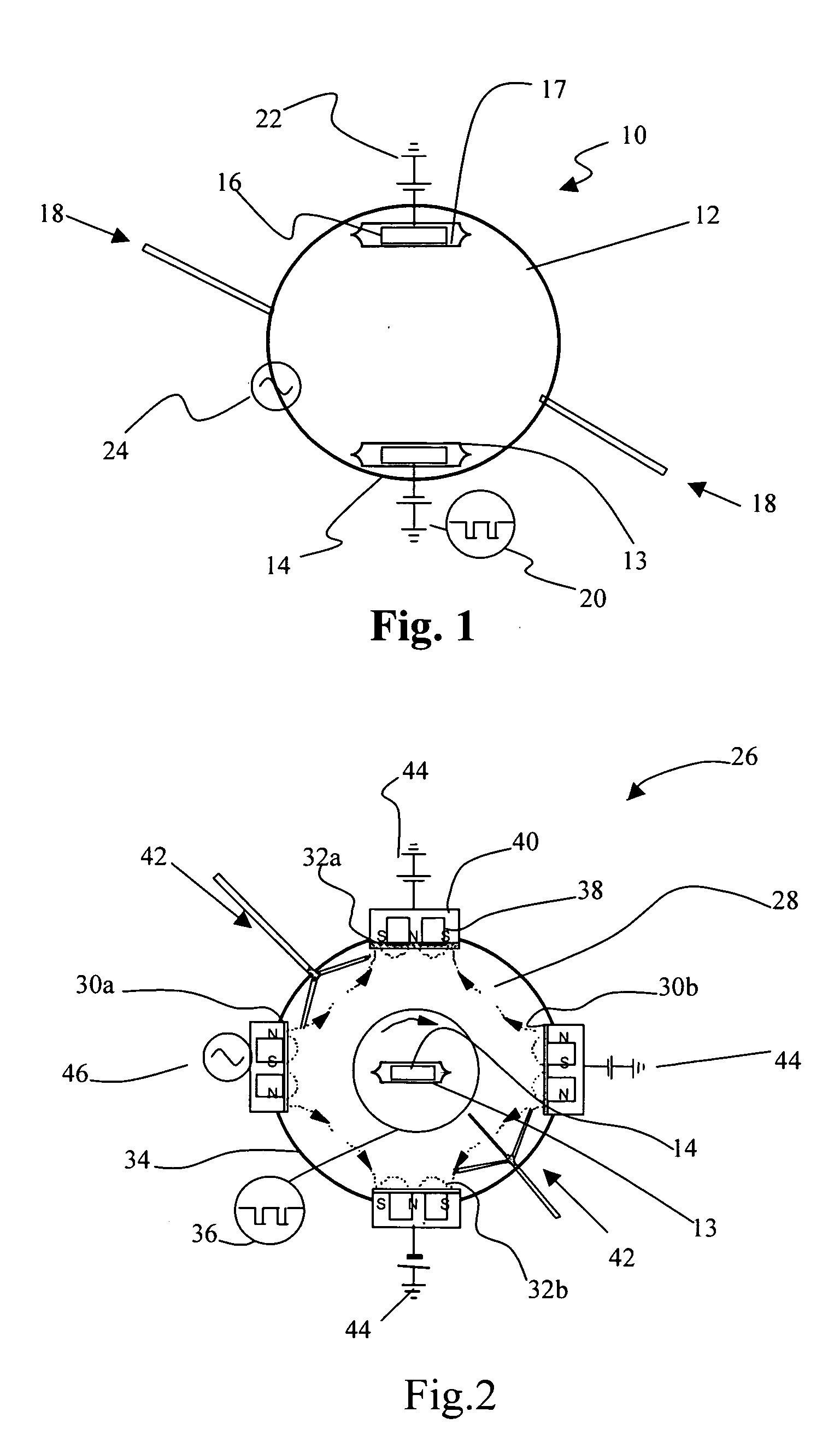
[0035] In the following example, a number of polished high-speed steel disks of 50 mm in diameter and 6 mm in thickness were used as substrates for deposition of coating samples to determine the characteristics of the coating by the current method. The pressure in the working chamber 28 was pumped down to below 1×10⁻⁵ Torr and each substrate was ultrasonically cleaned, followed by in situ Ar plasma cleaning with a pulse direct current (PDC) bias of −400 V and 300 kHz applied on the substrate for 10 to 30 minutes. Although the argon (Ar) gas flow during the deposition was set at a rate of 10 sccm, it can be varied. The substrate is rotated on the holder at a rate of 3-10 rpm and the substrate temperature is raised to a range between 150° C. and 300° C. by plasma bombardment, depending on the deposition time and the powers applied to the target and substrate.

[0036] According to the illustration in FIG. 2, chromium and titanium metal are used as targets 30a, 30b, 32a, and 32b. The tar...


PUM

PropertyMeasurementUnit
frequencyaaaaaaaaaa
thicknessaaaaaaaaaa
frequencyaaaaaaaaaa

Abstract

A method for coating a substrate surface where different types of powers are applied to the substrate and different targets. The method involves the formation of a layered structure in the coating where a metal layer is first formed, on top of which is an intermediate layer followed by a top functional layer which is chromium oxide composite. One of the power types is radio frequency power, used particularly for enhancing the efficiency of ionisation and decomposition of the reactive gases in the system. Another type of power, current that is controlled in a pulsed manner, is applied to substrate to improve the alignment of the deposited ions and atoms on the coating surface.

Description

TECHNICAL FIELD [0001] This invention relates to physical and chemical vapour deposition (PVD and CVD) of a coating for a surface. More particularly, this invention relates to a method of depositing a composite coating on a substrate surface. The coating may have anti-sticking properties and thus be suitable for use on mold surfaces for plastic encapsulation of integrated circuit (IC) packages. BACKGROUND OF THE INVENTION [0002] Integrated circuits (IC) are typically packaged in epoxy resins or epoxy molding compounds (EMC), which protects sensitive portions of the integrated circuits. The packaging of IC in these EMC uses IC encapsulation molds. A common problem that arises with the use of EMC is the tendency for these molding compounds to adhere to the encapsulation mold. Therefore the encapsulated IC package tends to stick to the encapsulation mold and prevents easy release of the IC packages from the encapsulation mold. Different types of EMC are used for their reliability and t...

Claims


Application Information

Patent Timeline
Patent Type & Authority Applications(United States)
IPC IPC(8): C23C14/34C23C14/00C23C14/02C23C14/06C23C14/08C23C16/00H01L21/44
CPCC23C14/0036C23C14/0057C23C14/3464C23C14/025C23C14/083C23C14/022
Inventor ZENG, XIAN TINGDING, XING ZHAO
Owner AGENCY FOR SCI TECH & RES
Why Eureka
Try Eureka