Electro-luminescence display device and driving apparatus thereof

Active Publication Date: 2005-06-30
LG DISPLAY CO LTD
View PDF9 Cites 13 Cited by
  • Summary
  • Abstract
  • Description
  • Claims
  • Application Information

AI Technical Summary

Benefits of technology

[0023] An advantage of the present invention is to provide an electro-luminescence display device and a driving apparatus thereof capable of preventing the deterioration of a thin film transistor, to thereby improve a quality of picture.
[0024] Additional features and advantages of the invention will be set forth in the description which follows, and in part will be apparent from the description, or may be learned by practice of the invention. The objectives and other advantages of the invention will be realized and attained by the structure particularly pointed out in the written description and claims hereof as well as the appended drawings.
[0025] To achieve these and other advantages and in accordance with the purpose of the present invention, as embodied and broadly described, an electro-luminescence (EL) display, including: a plurality of drive voltage supply lines; a plurality of compensation voltage supply lines; EL cells at each crossing of a plurality of data lines and a plurality of gate lines in a matrix, wherein the EL cells emit light in response to currents applied from the drive voltage supply lines; driving thin film transistors (TFT) connected between the EL cells and compensation voltage supply lines that control the current applied to the EL cells; and a bias switch, connected between the N−1th

Problems solved by technology

However, the driving thin film transistor deteriorates due to a continuous supply of a positive voltage to the gate terminal, and its current driving scheme.
As described above, if the threshold voltage of the driving thin film transistor is increased, the amount of current flowing to the EL cell OEL can not be accurately controlled, so that the luminance is decrease

Method used


Image

  • Electro-luminescence display device and driving apparatus thereof
  • Electro-luminescence display device and driving apparatus thereof
  • Electro-luminescence display device and driving apparatus thereof

Examples


Example

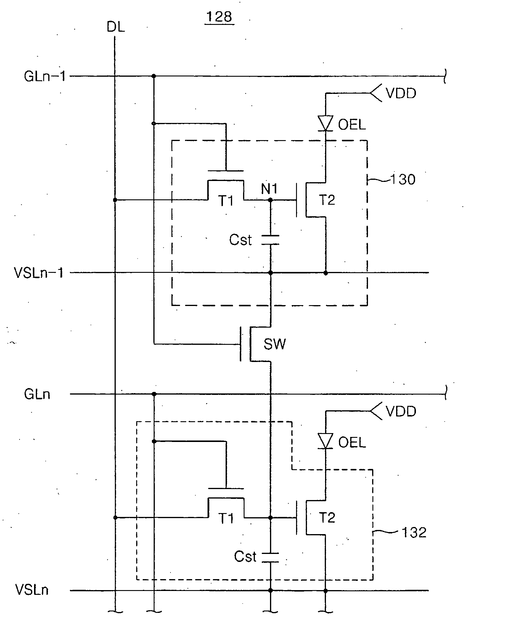
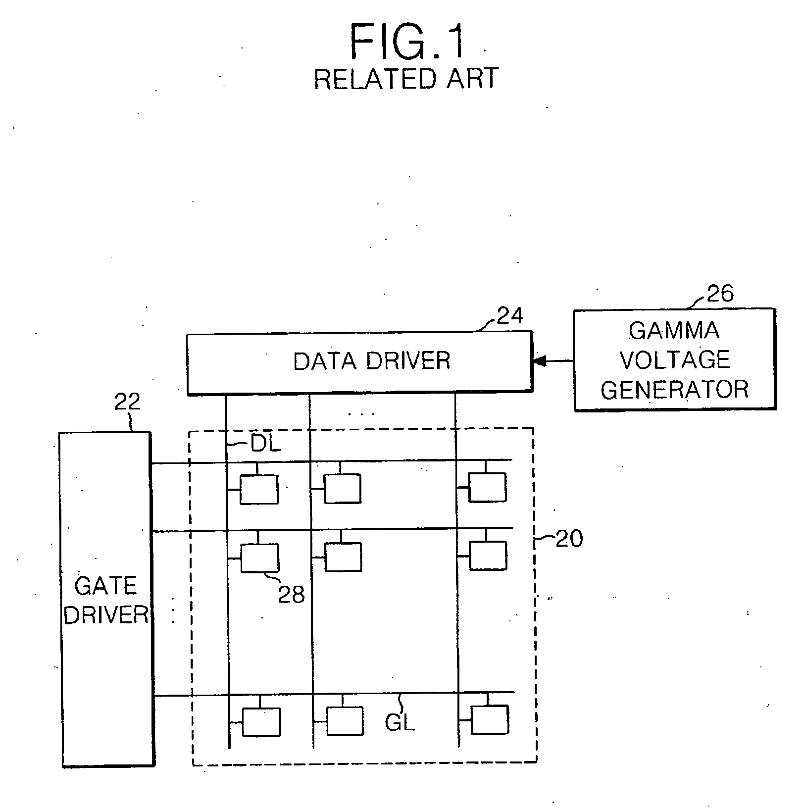
[0045]FIG. 5 illustrates an electro-luminescence display (EL) according to a first embodiment of the present invention. The EL display includes a EL panel 120 having a pixel arranged at each crossing between gate lines GL and data lines DL, a gate driver 122 driving the gate lines GL of the EL panel 120, a data driver 124 driving the data lines DL of the EL panel 120, a gamma voltage generator 126 supplying a plurality of gamma voltages to the data driver 124, a compensation voltage generator 125 generating a compensation voltage VSS, a shift register block 129 having a plurality of shift registers and sequentially supplying the compensation voltage from the compensation voltage generator 125 to a plurality of the compensation voltage supply lines VSL formed on the EL panel 120 and a plurality of bias switches SW connected between adjacent pixels in a vertical direction to supply the compensation voltage VSS from the compensation voltage supply line VSL to the pixels 128 of next sta...

Example

[0061]FIGS. 10 and 11 show an EL display according to a second embodiment of the present invention, which includes a EL panel 220 having a pixel arranged at each crossing between gate lines GL and data lines DL, a gate driver 222 driving the gate lines GL of the EL panel 220, a data driver 224 driving the data lines DL of the EL, a gamma voltage generator 226 supplying a plurality of gamma voltages to the data driver 224, a compensation voltage generator 225 generating a compensation voltage VSS, a plurality of bias switches SW connected between adjacent pixels 228 in a vertical direction to supply the compensation voltage VSS from the compensation voltage supply line VSLn-1 to the adjacent pixels 228 and a plurality of built-in switches PQ connected between the compensation voltage supply line VSL and the compensation voltage generator 225 and cutting-off the compensation voltage VSS supplied to the compensation voltage supply line VSL from the compensation voltage generator 225 de...

Example

[0073] With reference to FIGS. 12 and 13 show an EL display according to a third embodiment of the present invention, which includes a EL panel 320 having a pixel arranged at each crossing between gate lines GL and data lines DL, a gate driver 322 driving the gate lines GL of the EL panel 320, a data driver 324 driving the data lines DL of the EL panel 320, a gamma voltage generator 326 supplying a plurality of gamma voltages to the data driver 324, a compensation voltage generator 325 generating a compensation voltage VSS, a plurality of bias switches SW connected between adjacent pixels 328 in a vertical direction to supply the compensation voltage VSS from the compensation voltage supply line VSLn-1 to the adjacent pixels 328 and a plurality of built-in switches PQ connected between the compensation voltage supply line VSL and the pixel 328 depending upon the scan pulse supplied to the gate lines GL of previous stage.

[0074] In the EL display according to the third embodiment of ...


PUM


Abstract

The present invention relates to an electro-luminescence display and a driving method thereof wherein a thin film transistor is prevented from the deterioration, to thereby improve a picture quality. An electro-luminescence (EL) display, including: a plurality of drive voltage supply lines; N compensation voltage supply lines; EL cells at each crossing of a plurality of data lines and a plurality of gate lines in a matrix, wherein the EL cells emit light in response to currents applied from the drive voltage supply lines; driving thin film transistors (TFT) connected between the EL cells and compensation voltage supply lines that control the current applied to the EL cells; and a bias switch, connected between the N-1th compensation voltage supply line and a control terminal of the driving TFT connected to the Nth compensation voltage supply line that applies a bias voltage to the driving TFT when a scan pulse is supplied to the N-1th gate line.

Description

[0001] This application claims the benefit of Korean Patent Application No. P2003-99752, filed on Dec. 30, 2003, which is hereby incorporated by reference for all purposes as if fully set forth herein. BACKGROUND OF THE INVENTION [0002] 1. Field of the Invention [0003] This invention relates to an electro-luminescence display (ELD), and more particularly to an electro-luminescence display device and a driving apparatus thereof that prevents the deterioration of a thin film transistor to enhance image quality of the ELD. [0004] 2. Description of the Related Art [0005] Recently, various flat panel display devices have been developed that eliminate disadvantages of a cathode ray tube (CRT) by reducing the weight and bulk of the display. Such flat panel display devices include a liquid crystal display (LCD), a field emission display (FED), a plasma display panel (PDP) and an electro-luminescence (EL) display, etc. [0006] The EL display is a self-luminous device capable of emitting light...

Claims


Application Information

Patent Timeline
IPC IPC(8): G09G3/20H01L51/50G09G3/30G09G3/32H05B33/00H05B33/14
CPCG09G3/3233G09G3/3266G09G2300/0842G09G2320/043G09G2300/0866G09G2300/0876G09G2310/0254G09G2300/0861G09G3/30
Inventor LEE, HAN SANGKIM, SUNG KIKIM, HAE YEOLYOO, JUHN SUK
Owner LG DISPLAY CO LTD
Why Eureka
Try Eureka