Electroluminescence device, planar light source and display using the same

a technology of electric light source and light source, which is applied in the direction of instruments, discharge tube luminescnet screens, natural mineral layered products, etc., can solve the problems of not contributing to the enhancement of light extraction efficiency, and achieve the effects of improving light emission efficiency, low efficiency, and high light emission efficiency

Inactive Publication Date: 2005-06-30
NITTO DENKO CORP
View PDF32 Cites 186 Cited by
  • Summary
  • Abstract
  • Description
  • Claims
  • Application Information

AI Technical Summary

Benefits of technology

[0055] The present inventors have, however, selected the structural features of the device so that wide-angled beams of light which is usually confined within the device as waveguide light may be strengthened by one another, while the frontally directed beams of light are weakened, as is different from the above-mentioned conventional method, and formed a region for disturbing reflection / refraction angle of light after amplifying waveguide light having a distribution of the greater part of light, and found it possible to achieve an improved light-emitting efficiency over the prior art.
[0056] In other words, the present inventors have found that an organic EL device having the structural features mentioned above and also having a region for disturbing reflection / refraction angle eventually shows a higher light-emitting efficiency than when such a region is formed in any device of the known construction, while the organic EL device having the structural feature and not having the region has a low efficiency.

Problems solved by technology

With this method, however, only the light to be totally reflected at the air / glass interface can be extracted, and the light totally reflected at the interface between the glass substrate and the transparent electrode cannot even become incident on the region 8 and hence does not contribute to the enhancement of the light-extraction efficiency.

Method used


Image

  • Electroluminescence device, planar light source and display using the same
  • Electroluminescence device, planar light source and display using the same
  • Electroluminescence device, planar light source and display using the same

Examples


synthesis example 1-1

[0201] 29.89 g (171.6 mM) of tolylenediisocyanate (an isomer mixture: T-80, product of Mitsui Takeda Chemical Co.), 94.48 g (377.52 mM) of 4,4′-diphenylmethanediisocyanate, 64.92 g (308.88 mM) of naphthalenediisocyanate and 184.59 g of toluene were mixed in a 500 ml four-neck flask equipped with a stirrer, a dropping funnel, a reflux condenser and a thermometer. 8.71 g (51.48 mM) of 1-naphthylisocyanate and 0.82 g (4.29 mM) of 3-methyl-1-phenyl-2-phospholene-2-oxide were added to the mixture and under stirring, the whole was heated to 100° C. and held thereat for two hours. The progress of the reaction was ascertained by infrared spectroscopy. More specifically, observation was made of a decrease in absorption of the N—C—O stretching vibration of the isocyanate (2,270 cm−1) and an increase in absorption of the N—C—N stretching vibration of the carbodiimide (2,135 cm−1). The end point of the reaction was ascertained by IR and the reaction solution was cooled to room temperature to yi...

synthesis example 1-2

[0202] 89.01 g (355.68 mM) of 4,4′-diphenylmethanediisocyanate, 24.92 g (118.56 μM) of naphthalenediisocyanate, 44.87 g (266.76 mM) of hexamethylenediisocyanate and 216.56 g of toluene were mixed in a 500 ml four-neck flask equipped with a stirrer, a dropping funnel, a reflux condenser and a thermometer. 7.52 g (44.46 mM) of 1-naphthylisocyanate and 0.71 g (3.705 mM) of 3-methyl-1-phenyl-2-phospholene-2-oxide were added to the mixture, the whole was stirred at 25° C. for three hours and under stirring, the whole was then heated to 100° C. and held thereat for two hours. The progress of the reaction was ascertained by infrared spectroscopy, More specifically, observation was made of a decrease in absorption of the N—C—O stretching vibration of the isocyanate (2,270 cm−1) and an increase in absorption of the N—C—N stretching vibration of the carbodiimide (2,135 cm−1). The end point of the reaction was ascertained by IR and the reaction solution was cooled to room temperature to yield ...

example 1-1

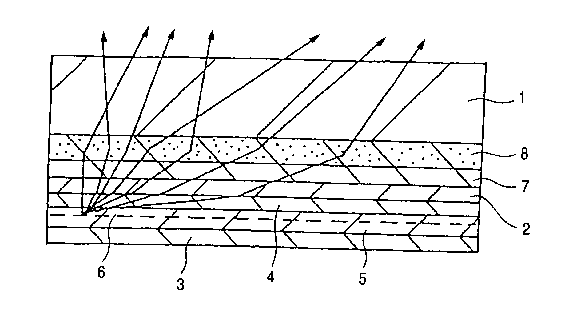
[0206] A toluene solution containing 70% by weight of silica particles having an average particle size of 0.5 μm was added to the polycarbodiimide resin solution as obtained in Synthesis Example 1-1 in the proportion of 20% by weight of the polycarbodiimide resin and the whole was stirred. The resulting dispersion was applied by an applicator to coat a glass substrate and was cured at 150° C. for one hour to form a transparent layer having a thickness of 25 μm and serving also as a light-diffusion layer on the glass substrate having a thickness of 1.1 mm. The refractive index of the glass substrate was measured with an Abbe refractometer and found to be 1.57 for the wavelength of 587.6 μm. The resulting sample had a haze of 87.3% as measured by a reflectance and transmittance meter (HR-100 of Murakami Color Research Laboratory).

[0207] Then, an ITO layer having a thickness of 100 nm was formed by DC sputtering from an ITO ceramic target (In2O3:SnO2=90% by weight:10% by weight) to fo...


PUM

PropertyMeasurementUnit
refractive indexaaaaaaaaaa
mean particle sizeaaaaaaaaaa
surface roughnessaaaaaaaaaa

Abstract

The present invention provides an organic electroluminescence device including an organic layer comprising an emissive layer; a pair of electrodes comprising an anode and a cathode, and sandwiching the organic layer, wherein at least one of the electrodes is transparent; a transparent layer provided adjacent to a light extracting surface of the transparent electrode; and a region substantially disturbing reflection and retraction angle of light provided adjacent to a light extracting surface of the transparent layer or in an interior of the transparent layer, wherein the transparent layer has a refractive index substantially equal to or more than the refractive index of the emissive layer.

Description

FIELD OF THE INVENTION [0001] The present invention relates to an electroluminescence device (hereinafter, referred to as “EL device”) which is excellent in light-emitting efficiency, and particularly excellent in extracting emitted light to the outside; and to a highly efficient planar light source using the EL device and a display using the same. BACKGROUND OF THE INVENTION [0002] An EL device, which includes an emissive layer sandwiched between a pair of electrodes consisting of an anode and a cathode, and from which light emission is electrically obtained, has been actively researched not only for application to a display device, but also for application to a variety of light sources, such as a flat-type illumination source, a light source for optical fiber, a backlight for liquid crystal display, or a backlight for a liquid crystal projector. [0003] Particularly, in recent years efforts have been focused on an organic EL device (Organic Light Emitting Diode), in view of its adv...

Claims


Application Information

Patent Timeline
Patent Type & Authority Applications(United States)
IPC IPC(8): H01L51/00H05B33/14H01L51/30H01L51/52H05B33/20H05B33/22
CPCG02B5/0242G02B5/0278H01L51/0052H01L51/0059H01L51/0062H01L51/0078Y10S428/917H01L51/5268H01L51/5275H01L2251/5369Y10T428/24942Y10T428/25H01L51/0081H10K85/649H10K85/615H10K85/631H10K85/311H10K85/324H10K50/854H10K50/858H10K2102/331H05B33/14H05B33/22H05B33/20
Inventor JUNI, NORIYUKINAKAMURA, TOSHITAKAHOTTA, YUJI
Owner NITTO DENKO CORP
Why Eureka
Try Eureka