Method of etching and etching apparatus
a technology of etching apparatus and etching method, which is applied in the direction of cleaning process and apparatus, chemistry apparatus and process, cleaning using liquids, etc., can solve the problem of partially damaged field oxide film placed beneath the si-containing film, and achieve the effect of reducing the damage to the substrate, and improving the etching rate of the si-containing film
- Summary
- Abstract
- Description
- Claims
- Application Information
AI Technical Summary
Benefits of technology
Problems solved by technology
Method used
Image
Examples
first preferred embodiment
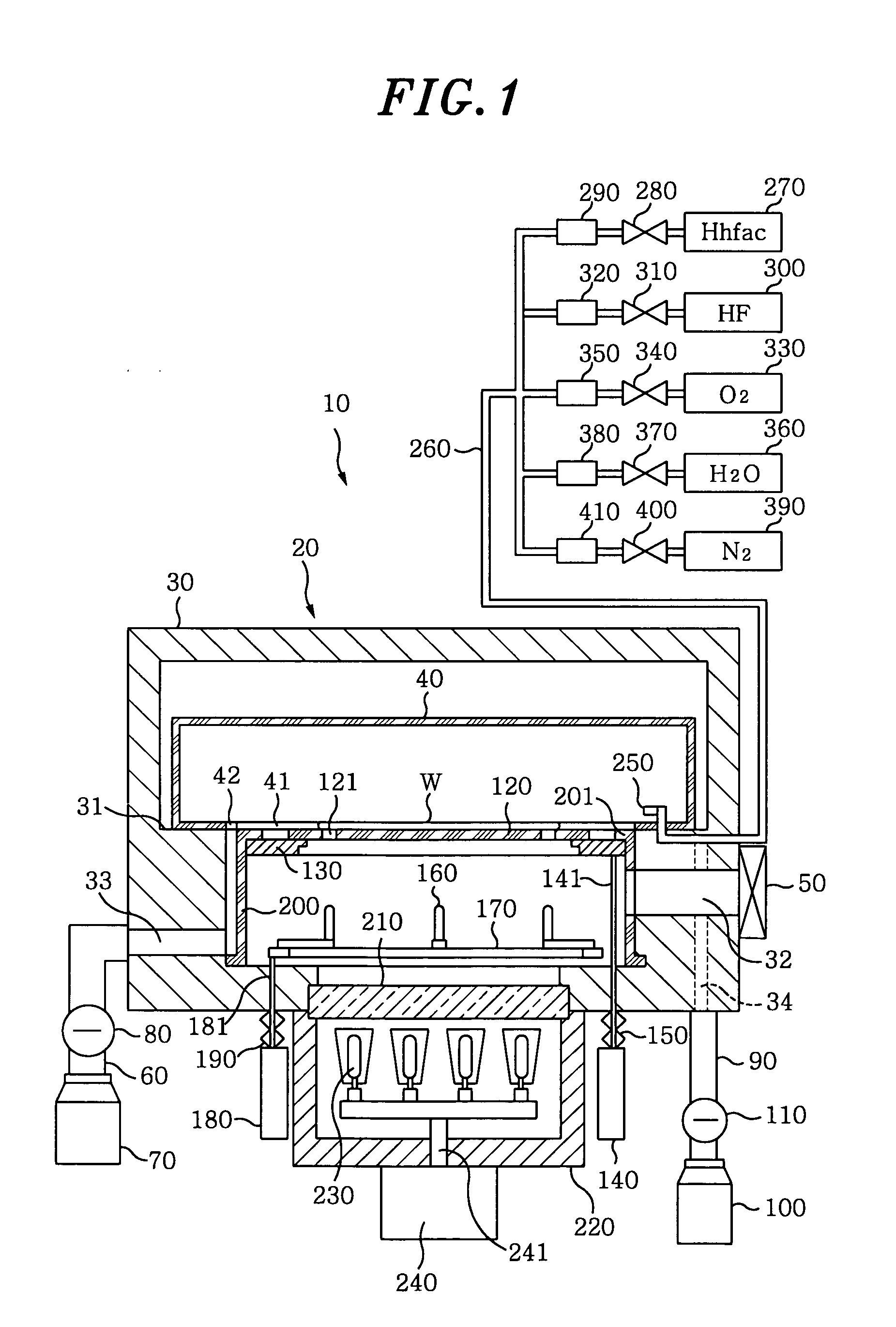
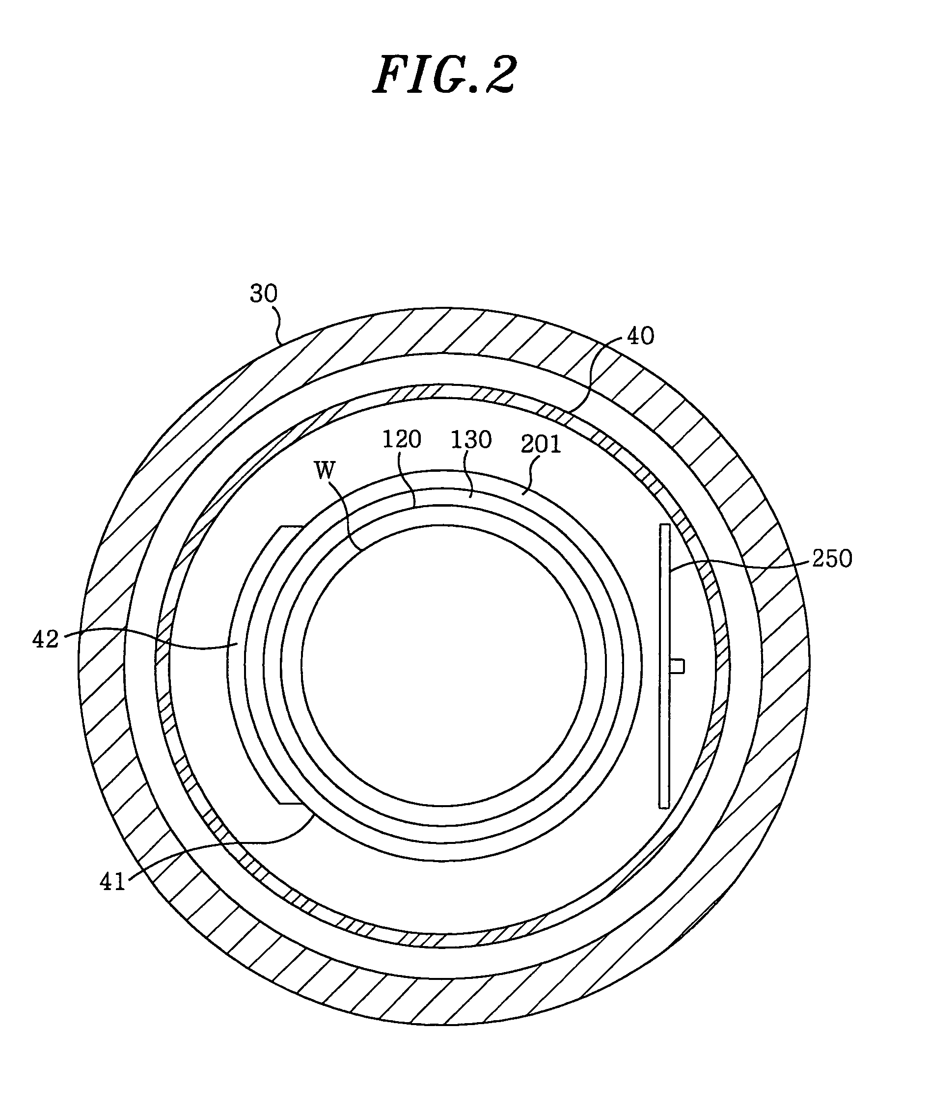
[0051] Hereinafter, a description will be given of an etching apparatus in accordance with a first preferred embodiment of the present invention. FIG. 1 schematically illustrates a vertical sectional view of the etching apparatus in accordance with the first preferred embodiment. FIG. 2 shows a top sectional view thereof; and FIG. 3 schematically illustrates a wafer before it is etched in accordance with the first preferred embodiment.
[0052] As shown in FIGS. 1 and 2, the etching apparatus 10 is equipped with a chamber 20 for housing a semiconductor wafer W. The chamber 20 includes an outer chamber 30 and an inner chamber 40, the inner chamber 40 being placed inside the outer chamber 30.
[0053] The outer chamber 30 is made of, e.g., Al. However, it can be made of hastelloy or the like and is not limited to Al in its construction. In addition, an inside wall of the outer chamber 30 may be subject to a surface treatment such as an alumite treatment or a PTFE (polytetrafluoroethylene)...
example 2 ; reference example 2
EXAMPLE 2; REFERENCE EXAMPLE 2
[0096] Hereinafter, a description will be given for Example 2 and Reference Example 2. An optimum temperature of a wafer when etching a HfO2 film was sought after.
[0097] The test conditions were as follows. The etching apparatus of the first preferred embodiment was used to etch the HfO2 film formed on a wafer. The HfO2 film was formed on the wafer while the wafer was maintained at a temperature of about 300° C. The etching gas contained Hhfac and O2, the flow rates thereof being 375 scam and 100 sccm, respectively. But H2O was not included in the etching gas. The pressure in the inner chamber was about 1.13×10⁴ Pa. While maintaining these conditions, the HfO2 films were etched at various wafer temperatures.
[0098] As Reference Example 2, HfO2 films formed at 150° C. were etched at various wafer temperatures. The HfO2 film formed at 300° C. is known to be denser than that formed at 150° C.
[0099] Results are summarized in FIG. 9 which shows the relatio...
example 3 ; reference example 3
EXAMPLE 3; REFERENCE EXAMPLE 3
[0101] Hereinafter, a description will be given for Example 3 and Reference Example 3. An optimum temperature of a wafer when etching an Al2O3 film was sought after.
[0102] The test conditions were as follows. The etching apparatus of the first preferred embodiment was used to etch the Al2O3 film formed on the wafer. The Al2O3 film was formed on the wafer while the wafer was maintained at a temperature of about 300° C. The etching gas contained Hhfac and O2, the flow rates thereof being 375 sccm and 100 sccm, respectively. But H2O was not included in the etching gas. The pressure in the inner chamber was about 1.13×10⁴ Pa. While maintaining these conditions, the Al2O3 films were etched at various wafer temperatures.
[0103] As Reference Example 3, the Al2O3 film formed at 150° C. was etched at various wafer temperatures.
[0104] The results are summarized in FIG. 10 which shows the relationship between the etching rate of the Al2O3 film and the temperatur...
PUM
 Abstract
Description
Claims
Application Information
 - R&D
- Intellectual Property
- Life Sciences
- Materials
- Tech Scout
- Unparalleled Data Quality
- Higher Quality Content
- 60% Fewer Hallucinations
Browse by: Latest US Patents, China's latest patents, Technical Efficacy Thesaurus, Application Domain, Technology Topic, Popular Technical Reports.
© 2025 PatSnap. All rights reserved.Legal|Privacy policy|Modern Slavery Act Transparency Statement|Sitemap|About US| Contact US: help@patsnap.com


