Patient comfort apparatus and system

Inactive Publication Date: 2005-06-30
GEN ELECTRIC CAPITAL +1
View PDF83 Cites 122 Cited by
  • Summary
  • Abstract
  • Description
  • Claims
  • Application Information

AI Technical Summary

Benefits of technology

[0015] The invention is based upon the critical realization that garments presently available for use on ambulatory patients can be adapted to provide thermal comfort when combined with a pneumatic convective device. In this regard, lightweight robes or gowns which open at the back or a side, are worn with an open bottom like a skirt or kilt, and are supported primarily at the shoulders and/or neck of the users are referred to as “clinical garments”. These clinical garments afford mobility for users; they also provide convenience for clinicians during examination in that they may be easily moved, adjusted, removed, and put back on. Accordingly, the invention provides pneumatic convective thermal treatment of the feeling of being cold by means of pneumatic convective devices

Problems solved by technology

Because these devices are designed to cover and hang about or over a supine person, they are not easily or readily deployed on persons who are standing, sitting, reclining or moving.
In particular, inflatable blankets are not suitable in a clinical setting in which it is desirable to warm a patient, and also necessary that the patient be able to move about and between various postures.
Further, patient mobility throughout a clinic or a hospital is highly desirable, but would be severely curtailed with use of inflatable blankets.
For example, transporting a patient to an x-ray or MRI location in a wheelchair, would be made problematic with an inflatable blanket.
However, this adaptation has a limited use in that a person using it must remain in a sitting or reclining posture in order for the device to drape over the person's body and retain warmed air and heat about the person.
Such devices are not designed to accommodate movement or changes in the pe

Method used


Image

  • Patient comfort apparatus and system
  • Patient comfort apparatus and system
  • Patient comfort apparatus and system

Examples


Example

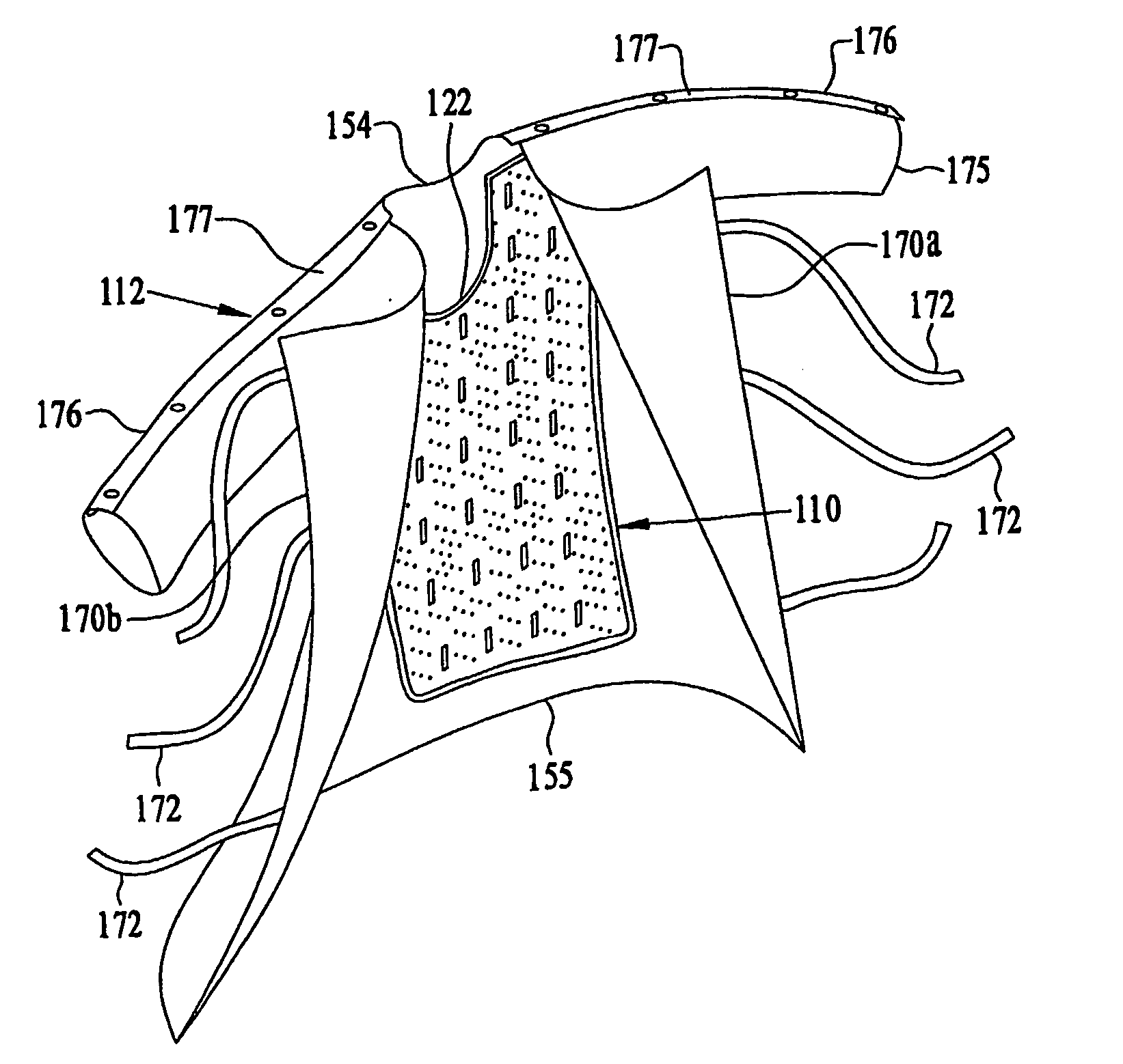
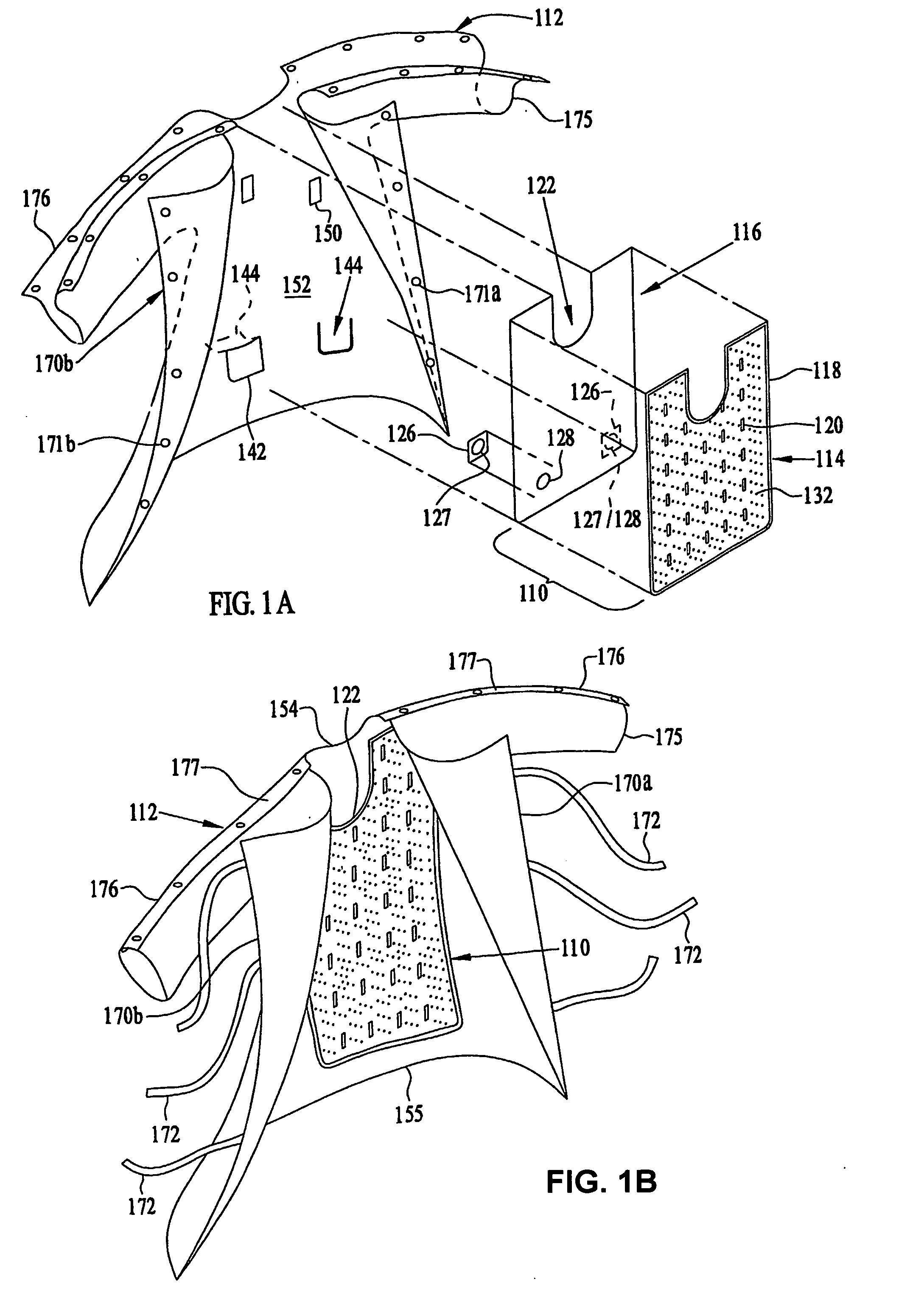
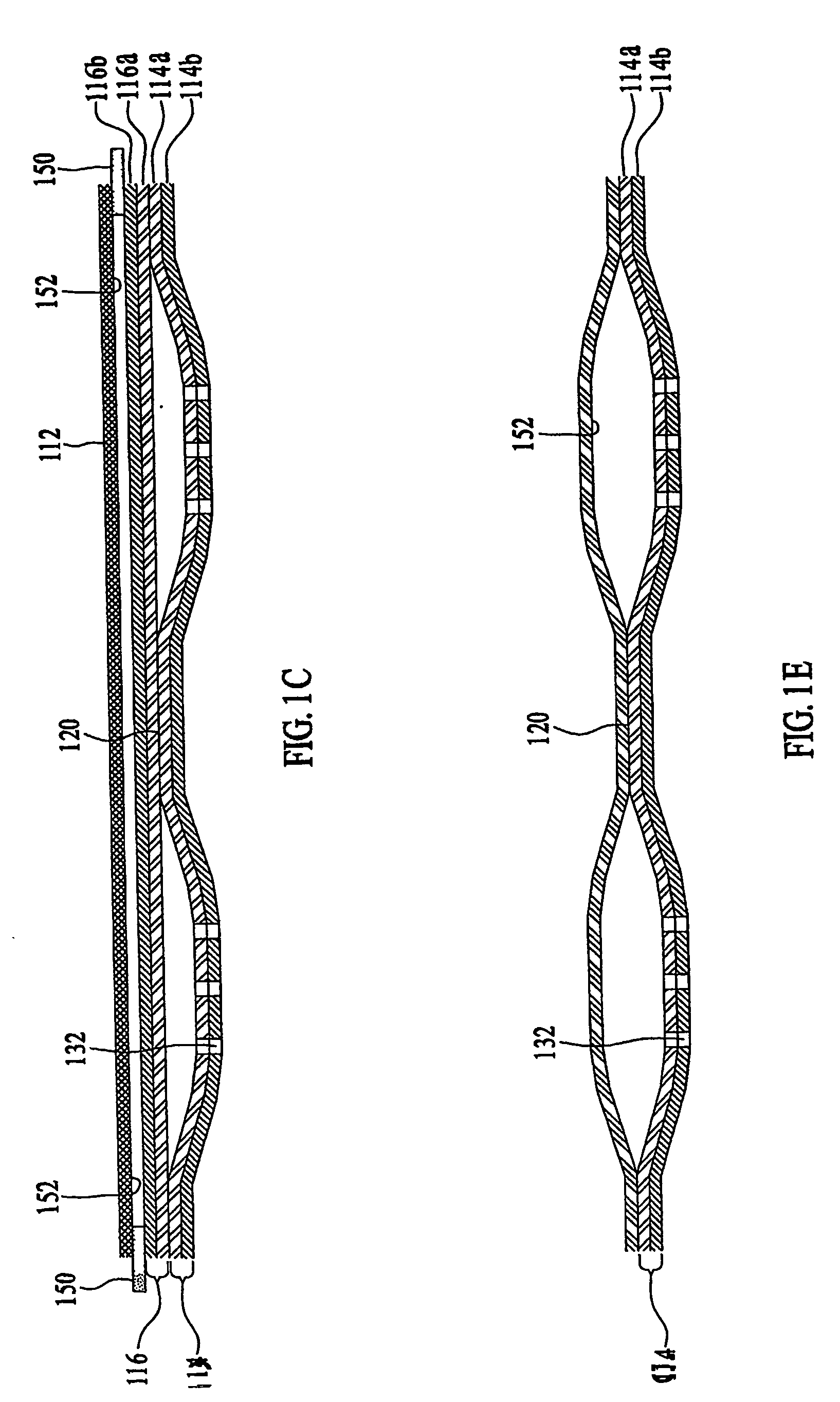
[0023] The invention is embodied as a pneumatic convective device receivable on a human or animal body in a clinical setting which receives a stream of pressurized, thermally conditioned air, distributes the pressurized air within a pneumatic structure, and emits the air through one or more surfaces for convective transfer of heat between the thermally conditioned air and the body. The invention is further embodied as a pneumatic convective device combined with a clinical garment to thermally comfort a patient in a clinical setting. Various specific embodiments of the invention are illustrated and discussed according to an example in which a human body is warmed by focusing or concentrating convective warming on the body core in order to permit patient movement and to enhance clinical convenience, although this is not intended to suggest that the invention may not be used for cooling, which, indeed, it may.

[0024] Further, use of the term “convective” to denote the transfer of heat ...


PUM

PropertyMeasurementUnit
Lengthaaaaaaaaaa
Permeabilityaaaaaaaaaa
Distributionaaaaaaaaaa

Abstract

Apparatus and a system for thermally comforting a patient include pneumatic, convective providing thermal treatment for persons or animals, which is adapted for use in combination with a clinical garment such as a hospital gown, robe, bib, and other equivalents. The pneumatic convective device provides convective warming focused or directly primarily on the thorax or body core. The pneumatic convective device includes at least one inlet for being accessed through a clinical garment, a region in distribution with the inlet for distributing a stream of pressurized, thermally treated air, and a permeable member for emitting pressurized, thermally treated air from the distribution region.

Description

CROSS REFERENCE TO RELATED APPLICATIONS [0001] This application claims the benefit of U.S. Provisional Application No. 60 / 371,314 filed Apr. 10, 2002. [0002] This application contains subject matter related to that of U.S. patent application Ser. No. ______ for “FORCED AIR WARMING UNIT” and U.S. patent application Ser. No. ______, for “PATIENT COMFORT APPARATUS AND SYSTEM”, filed concurrently with this application, and to that of U.S. Design patent application Ser. No. ______, for “FORCED AIR WARMING UNIT”.BACKGROUND OF THE INVENTION [0003] 1. Field of the Invention [0004] The invention is directed to a patient comfort system that includes pneumatic convective devices receivable on a human or animal body which receive a stream of pressurized, thermally conditioned air, distribute the pressurized air within a pneumatic structure, and emit the air through one or more surfaces for convective transfer of heat between the thermally conditioned air and the body. In particular, the inventi...

Claims


Application Information

Patent Timeline
IPC IPC(8): A41D13/12A41D13/00A41D27/22A61F7/00A61F7/02
CPCA61F7/00A41D2400/32A61F7/02A61F2007/0018A61F2007/006A61F2007/0091A61F2007/0094A61F2007/0234F16L31/00F16L37/098A61F2310/0097A61F7/0085A41D13/0025A41D2400/14A61F7/0097
Inventor AUGUSTINE, SCOTT D.ANDERSON, THOMAS PETERARNOLD, RANDALL CHARLES
Owner GEN ELECTRIC CAPITAL
Why Eureka
Try Eureka